Harman Kardon ABH 4 Owners Manual - Page 3
Local IR Input Terminals - manual
 |
View all Harman Kardon ABH 4 manuals
Add to My Manuals
Save this manual to your list of manuals |
Page 3 highlights
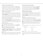
Typographical Conventions To help you use this manual, the following typographical conventions are used to identify the various parts of the product. ¡ (number in a circle) Indicates a connection point on the side edges of the ABH 4. å (letter in a circle) Indicates an LED indicator on the top face of the ABH 4. Top-Edge Connections ¡ Status Input: When the ABH 4 is used in the stand-alone mode with a non-A-BUS/READY source or receiver, an optional 12-volt DC power source may be attached to this jack to keep the A-BUS system active. ™ Power Input: Connect the small mini plug at the end of the ABH 4 power supply to this jack. £ Audio Inputs: When the ABH 4 is used in the stand-alone mode to create an A-BUS system using a receiver that is not A-BUS/READY, connect the right and left audio outputs from the feed source to these input jacks. The source may be a single product such as a tuner or CD player, or it may be the Tape outputs or Multiroom outputs of a receiver. Note that these inputs are connected to Music Sense circuitry that will automatically turn on all A-BUS modules connected to the ABH 4 when an audio signal is present, and turn them off 30 seconds after the audio signal stops. ¢ Expansion In Jack: This jack connects to the device that is providing the A-BUS system source that feeds the A-BUS modules used with this ABH 4. In most applications, the connection will be to the A-BUS output on a Harman Kardon A-BUS/READY receiver, although the input may also come from the Expansion Out Jack ∞ of another ABH 4 when multiple hubs are in use. In all cases, the connection should be made using a standard TIA 568A RJ-45 jumper cable. ∞ Expansion Out Jack: If you are using more than one ABH 4 in your system to add additional rooms, connect one end of a jumper cable with RJ-45 connectors to this jack. Connect the other end of the jumper cable to the Expansion In Jack ¢ on the next ABH 4. Bottom-Edge Connections § Local IR Input Terminals: When the ABH 4 is used with a source product other than an A-BUS/READY receiver, these terminals allow you to connect a compatible, optional IR receiver/sensor to receive infrared remote commands for the control of source components in a room where there is no A-BUS module. IR commands received by the sensor will be retransmitted to the IR Emitter Jacks ¶ for use with optional IR emitters. Follow the instructions packed with the IR receiver/sensor for the proper connections to the terminals here. To connect wires from the sensor, unscrew the retaining screw on the appropriate terminal until wire clamp retracts into the bottom of the terminal block. Insert the wires following the instructions in Step Seven on the other side of this sheet, and tighten the screw until the clamp secures the wire so that it does not fall out. ¶ IR Emitter Jacks: These jacks route the IR signals that are received either by the remote sensor in an A-BUS module such as Harman Kardon's AB 1 or from an optional IR receiver connected to the Local IR Input Terminals § to optional remote IR emitters. These emitters should be placed over the IR receiver in the source components to be controlled in accordance with their manufacturer's instructions. This enables a remote control where an A-BUS module is installed to control source components such as a CD or DVD player. • A-BUS Outputs: These jacks are the communications link between the remote A-BUS modules and the ABH 4, carrying audio signals and power to the A-BUS modules, and IR commands from the A-BUS modules to the ABH 4 and products connected to it. Connect a cable from each remote A-BUS module to these outputs using standard RJ-45 connectors with cabling wired in compliance with the TIA 568A standard. LED Indicators å Status Indicator: This LED will light when the ABH 4 is activated. In most cases, it will light when a Harman Kardon A-BUS/READY receiver connected to the ABH 4 is turned on. When the ABH 4 is used with non-A-BUS/READY products, the Status Indicator will light when an audio signal is present at the Audio Inputs £ or when a DC power source is connected to the Status Input ¡. The Status Indicator will go out 30 seconds after the power or audio source is removed. ∫ Power Indicator: This LED will light to indicate that the ABH 4 is connected to a power source that enables the remote modules and the infrared relay system to operate. This power source may be either a connection to an A-BUS/READY prod¡uct, th™e ABH 4's p£ ower supply o¢ r thro∞ ugh a connection to another ABH 4. Note that the ABH 4's external power supply must be connected in order for it to power multiple remote modules. ç IR Indicator: This LED will flash to confirm that an IR signal is being passed through the ABH 4. This signal may originate from a remote A-BUS module or from an optional remote sensor attached to the Local IR Input Terminals §. ¡™ £ ¢∞ å ∫ ç å ∫ ç ¡™ £ ¢∞ • ¶ § å ∫ ç • ¶ § 2
-
 1
1 -
 2
2 -
 3
3 -
 4
4 -
 5
5 -
 6
6 -
 7
7 -
 8
8 -
 9
9
 |
 |
