Harman Kardon ABH 4 Owners Manual - Page 8
Specifications, Operation, Status Input, Audio Inputs, Status Indicator, Status Inputs, Power
 |
View all Harman Kardon ABH 4 manuals
Add to My Manuals
Save this manual to your list of manuals |
Page 8 highlights
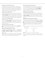
Operation When the installation is complete and all connections have been made to the ABH 4 and receiver, processor or preamplifier, and the A-BUS modules have been properly installed in the remote rooms, operation of the ABH 4 is simple. There are no user controls on the ABH 4. After checking the connections, plug the AC power cord from the ABH 4's Power Supply into a non-switched AC outlet and turn on the host receiver, processor or preamplifier. Operation of the ABH 4 is seamless, as the remote A-BUS modules will communicate directly with the host source. When the ABH 4 is used with an A-BUS/READY receiver, the A-BUS modules in the remote room operate as if they were connected directly to the host receiver. No further controls are needed. Follow the instructions included with the A-BUS modules for operation information. When the ABH 4 is used in the stand-alone mode with a source that is not A-BUS/READY, the method of operation varies depending on the specifics of the installation: • When a 12-volt adaptor is not connected to the ABH 4's Status Input ¡, the system is able to pass through IR commands from the remote modules to turn on the host receiver, processor or preamplifier, but there is no power to a remote module's internal amplifier until an audio signal is sensed at the ABH 4's Audio Inputs £. • When a 12-volt adaptor is connected to the ABH 4's Status Input ¡, the system is ready for full operation at all times, including pass-through of IR commands from remote A-BUS modules as well as power to the remote modules' internal amplifiers. The three LED indicators on the ABH 4 signify the following operational modes: • The Status Indicator å lights when the system is activated either by connection to an A-BUS/READY receiver that is turned on, when a signal is sensed at the Audio Inputs £ or when a 12-volt power source is connected to the Status Inputs ¡. This light indicates that the remote modules are active and ready to accept and transmit commands. • The Power Indicator ∫ lights when the AC Power Supply is connected to the ABH 4 and/or when a connection is made between the ABH 4 and an A-BUS/READY receiver. This light indicates that the system is powered on and is operational. • The IR Indicator ç flashes whenever an IR command is transmitted through the system. Troubleshooting Guide If the remote A-BUS modules do not operate at all: • Verify all connections between the remote modules and the ABH 4 • Check the RJ-45 connection between the ABH 4 and the host receiver (A-BUS/READY systems) • Check the AC power connection at both the ABH 4's Power jack and on the Power Supply If the remote module's status LED is lit but there is no sound: • Make certain that an active source has been selected on the host receiver • Check the RJ-45 connection between the ABH 4 and the host receiver (A-BUS/READY systems) • Check the audio connections between the ABH 4 and the host receiver (non-A-BUS/READY systems) For additional troubleshooting information and updated operational and installation hints, please visit the Product Support section of the Harman Kardon Web site at www.harmankardon.com. Specifications ABH 4 Dimensions (D x W x H): 3-5/16" x 7-3/16" x 1-3/16" (83mm x 184mm x 30mm) Weight: 0.9 lb (410g) Power Supply Dimensions (D x W x H): 2-13/16" x 5-15/16" x 1-7/16" (70mm x 151mm x 36mm) Weight: 1 lb (450g) Power Supply Input: 108 - 264 VAC, 115 watts Power Supply Output: 24-volt, 4-amp supply included Status Power: 12 volts, 200ma Wiring protocol for A-BUS connections: TIA wiring specification for TIA 568A ¡™ £ ¢∞ ¡™ £ ¢∞ Top-Edge Connections å ∫ ¡ Status Input çå ™ Power Input ∫ £ Audio Inputs ç ¢ Expansion In Jack ∞ Expansion Out Jack ¶¢ ∞ § B¶ottom-Edge §Connections § Local IR Input Terminals ¶ IR Emitter Jacks • A-BUS Outputs å ∫ ç LED Indicators å Status Indicator ∫ Power Indicator ç IR Indicator 7
-
 1
1 -
2
-
 3
3 -
 4
4 -
 5
5 -
 6
6 -
 7
7 -
 8
8 -
 9
9
 |
 |
