Harman Kardon AVR 8000 Owners Manual - Page 9
Rear Panel Connections - for no sound
 |
View all Harman Kardon AVR 8000 manuals
Add to My Manuals
Save this manual to your list of manuals |
Page 9 highlights
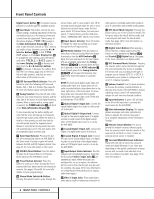
Rear Panel Connections , Surround Back Preamp Outputs: When the AVR is used in the 6.1 or 7.1 configuration, connect these jacks to an optional, external power amplifier to power the Surround Back Channels. ⁄ Tape Inputs: Connect these jacks to the PLAY/OUT jacks of an audio recorder. ¤ Component Video Outputs: Connect these outputs to the component video inputs of a video projector or monitor. When a source connected to one of the Component Video Inputs ‹› is selected the signal will be sent to these jacks. ‹ Video 1/Video 2 Component Video Inputs: Connect the Y/Pr/Pb component video outputs of an HDTV Set-top convertor, satellite receiver, or other video source device with component video outputs to these jacks. › DVD Component Video Inputs: Connect the Y/Pr/Pb component video outputs of a DVD player to these jacks. fi AC Power Cord Jack: Connect the AC Power cord to this jack when the installation is complete. To ensure safe operation, use only the power cord supplied with the unit. If a replacement is required it must be of same type and capacity. fl Unswitched AC Accessory Outlet: This outlet may be used to power any AC device. The power will remain on at this outlet regardless of whether the AVR 8000 is on or off. NOTE: The total power consumption of all devices connected to the accessory outlets should not exceed 100 watts. ‡ Switched AC Accessory Outlets: These outlets may be used to power any device you wish to have turned on when the AVR 8000 is turned on with the System Power Control Button 2. ° Center Speaker Outputs: Connect these outputs to the matching + and - terminals on your center channel speaker. In conformance with the new CEA color code specification, the Green Terminal is the positive, or "+" terminal that should be connected to the red (+) terminal on speakers with the older color coding. Connect the black (-) terminal on the AVR to the black negative (-) terminal on your speaker. (See page 15 for more information on speaker polarity.) · 8-Channel Direct Inputs: When an optional, external source with discrete 7.1 analog audio output capability such as a DVDAudio or SACD player is use, connect that unit's surround back output jacks here. a Coaxial Digital Audio Output: Connect this jack to the coaxial digital input of a CD-R/RW, MiniDisc or other digital recorder. b Coaxial Digital Inputs: Connect the coax digital output from a DVD player, HDTV receiver, the S/P-DIF output of a compatible computer sound card playing MP3 files or streams, LD player or CD player to these jacks. The signal may be either a Dolby Digital signal, DTS signal or a standard PCM digital source. Do not connect the RF digital output of an LD player to these jacks. c 6-Channel Direct Inputs: When an optional, external source with discrete 5.1 analog audio output capability such as a DVD-Audio or SACD player is use, connect that unit's output jacks here. NOTE: To assist in making the correct connections for multichannel input output and speaker connections, all connection jacks and terminals have been color coded in conformance with the latest CEA standards as follows: Front Left: White Front Right: Red Center: Green Surround Left: Blue Surround Right: Gray Surround Back Left: Brown Surround Back Right: Tan Subwoofer: Purple Digital Audio: Orange Composite Video: Yellow Component Video "Y": Green Component Video "Pr": Red Component Video "Pb": Blue d Optical Digital Audio Output: Connect this jack to the optical digital input connector on a CD-R/RW, MiniDisc or other digital recorder. e Optical Digital Inputs: Connect the optical digital output from a DVD player, HDTV receiver, the S/P-DIF output of a compatible computer sound card playing MP3 files or streams, LD player or CD player to these jacks. The signal may be either a Dolby Digital signal, a DTS signal or a standard PCM digital source. f DVD Inputs: Connect the analog left/right audio and composite or S-Video output of a DVD player or other video source to these jacks. g Amplifier Trigger Jack: Connect this jack to the compatible input trigger jack on a power amplifier or other relay controlled device. The connected product will turn on when the AVR is turned on. h Multizone IR Input: Connect the output of an IR sensor in a remote room to this jack to operate the AVR 8000's multiroom control system. i Remote IR Input: If the AVR 8000's front-panel IR sensor is blocked due to cabinet doors or other obstructions, an external IR sensor may be used. Connect the output of the sensor to this jack. j Remote IR Output: This connection permits the IR sensor in the receiver to serve other remote controlled devices. Connect this jack to the "IR IN" jack on Harman Kardon (or other compatible) equipment. k Video 1/Video 2 Inputs: Connect the left/right audio and composite or S-Video PLAY/OUT jacks on a VCR or other video source to these jacks. 31 Video 3/Video 4 Inputs: Connect the left/right audio and composite or S-Video outputs of a video source such as a VCR, satellite receiver, hard drive video recorder or other device to these jacks. 32 Multizone Outputs: Connect these jacks to the optional external audio power amplifier and video distribution system that delivers the source selected for multizone distribution. 33 Video 1/Video 2 Outputs: Connect the left/right audio and composite or S-Video Record/Input jacks on a VCR or camcorder to these jacks. 34 Video Monitor Outputs: Connect these jacks to the composite or S-Video input of a TV monitor or video projector to view the on-screen menus and the output of any standard video source selected by the receiver's video switcher. 9 REAR PANEL CONNECTIONS
-
 1
1 -
2
-
3
-
 4
4 -
 5
5 -
 6
6 -
 7
7 -
 8
8 -
 9
9 -
 10
10 -
 11
11 -
 12
12 -
 13
13 -
 14
14 -
15
-
16
-
17
-
18
-
19
-
20
-
21
-
22
-
23
-
24
-
25
-
26
-
27
-
28
-
29
-
30
-
31
-
32
-
33
-
34
-
35
-
36
-
37
-
38
-
39
-
40
-
41
-
42
-
43
-
44
-
45
-
46
-
47
-
48
-
49
-
50
-
51
-
52
-
53
-
54
-
55
-
56
-
57
-
58
-
59
-
60
 |
 |
