Hayward OnCommand Model: ALL MODELS Installation
Hayward OnCommand Manual
 |
View all Hayward OnCommand manuals
Add to My Manuals
Save this manual to your list of manuals |
Hayward OnCommand manual content summary:
- Hayward OnCommand | Model: ALL MODELS Installation - Page 1
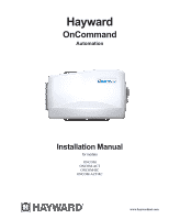
Hayward OnCommand Automation Installation Manual for models ONCOM ONCOM-ACT ONCOM-RC ONCOM-ACT-RC www.haywardnet.com - Hayward OnCommand | Model: ALL MODELS Installation - Page 2
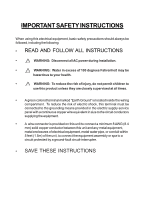
they are closely supervised at all times. • A green colored terminal marked "Earth Ground" is located inside the wiring compartment. To reduce the risk of electric shock, this terminal must be connected to the grounding means provided in the electric supply service panel with a continuous copper - Hayward OnCommand | Model: ALL MODELS Installation - Page 3
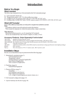
Contents Introduction 1. Mounting Equipment 2. Plumbing 3. Electrical Wiring 4. Configuration 5. System Startup and Checkout 6. Warranty Before You Begin 1 Installation Steps 1 OnCommand Control Center 2 Temperature Sensors 2 Wireless Remote Control 2 Base Station 3 Optional Valve Actuators - Hayward OnCommand | Model: ALL MODELS Installation - Page 4
installation step are presented on the following pages: 1. Mounting the equipment (page 2) OnCommand main unit Temperature sensors Wireless Remote Controls (if applicable) Base Station (if applicable) Valve actuators (if applicable) 2. Plumbing (page 4) General Pool Equipment 3. Electrical Wiring - Hayward OnCommand | Model: ALL MODELS Installation - Page 5
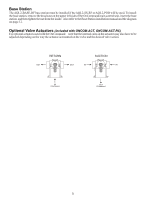
the base station on the OnCommand main control unit is 400 feet (120m) line of sight or 200 feet (60m) through walls, etc. If in doubt about the distance, test operation before installing the remote. Wireless remote controls require the user to run the "Teach Wireless" routine in the Settings Menu - Hayward OnCommand | Model: ALL MODELS Installation - Page 6
the upper left side of the OnCommand main control unit, insert the base station, and then tighten the nut from the inside. Also refer to the Base Station installation manual and the diagram on page 12. Optional Valve Actuators (included with ONCOM-ACT, ONCOM-ACT-RC) For optional actuators used with - Hayward OnCommand | Model: ALL MODELS Installation - Page 7
the OnCommand control of Standard Pool/Spa systems (refer to the Operation section for more information): In Pool/Spa Config., select: Pool/Spa Setup Pool and Spa 1. The OnCommand can be programmed to accommodate spa spillover, if desired. 2. A conventional heater (gas or heat pump) and solar - Hayward OnCommand | Model: ALL MODELS Installation - Page 8
the primary electrical panel to this ground bus bar. Also use this ground bar to ground each piece of high voltage (120 or 240VAC) equipment that is connected to the OnCommand control relays. High Voltage Wiring Input Wiring The OnCommand requires 120VAC, .6A input power to operate the control logic - Hayward OnCommand | Model: ALL MODELS Installation - Page 9
. 240 VAC Load 120 VAC Load 120 VAC Load Wiring relays for 240 VAC Pool Equipment Wiring relays for 120 VAC Pool Equipment Wiring GFCB for 120 VAC Pool Equipment ! WARNING: Do not use the OnCommand to control an automatic pool cover. Swim- mers may become entrapped underneath the cover. 6 - Hayward OnCommand | Model: ALL MODELS Installation - Page 10
source to the "Lights" relay and then connect the color wheel to one of the AUX outputs. Hayward Variable Speed Filter Pump: Proper installation of the Hayward TriStar Variable Speed Control (VSC) includes high voltage input wiring, communication wiring, and menu configuration/settings. Refer to the - Hayward OnCommand | Model: ALL MODELS Installation - Page 11
manuals supplied with most heaters also include specific wiring instructions for connecting the heater to an external control (usually identified as "2-wire" remote control). For millivolt or line voltage heaters, contact Goldline Tech support, 908-355-7995. Refer to the diagrams and the information - Hayward OnCommand | Model: ALL MODELS Installation - Page 12
white remove jumper white Fusible Link Hayward Heaters Refer to the instructions in the heater manual for "2-wire Remote Thermostat" operation under "Remote Control Connections" and the diagram below: 1. Turn off power to heater. 2. Wire OnCommand to terminals 1 & 2 (see diagram). 3. Leave jumper - Hayward OnCommand | Model: ALL MODELS Installation - Page 13
heater. 2. Remove factory installed jumper from the "Ext Switch" connector. 3. Wire the OnCommand to the "Ext Switch" connector as shown below. 4. The wires to the OnCommand must be separated from any line voltage wires. Failure to follow these instructions may cause erratic operation of the heater - Hayward OnCommand | Model: ALL MODELS Installation - Page 14
off to heater. 2. Remove upper jacket and open the control box. 3. Remove the jumper for the "fireman's switch. 4. Wire to the OnCommand using wire rated for 105°C minimum. Fireman's Switch Operating 'Control Terminal Board STA-RITE Hayward Variable Speed Filter Pump: Refer to the diagram below - Hayward OnCommand | Model: ALL MODELS Installation - Page 15
suitable cable types and splices. See page 2 and the diagram below for installation information. POOL/SPA SENSOR AIR SENSOR SOLAR SENSOR optional Base Station Plug in the pigtail connector from the wireless base station into the "wireless" connector on the main PCB in the OnCommand control unit. 12 - Hayward OnCommand | Model: ALL MODELS Installation - Page 16
of commands that are programmed in the Configuration Menu. For example, instead of the Lights button turning on and off the pool light only, the button can be programmed to turn on the pool light, turn on the bug light, turn off the pool cleaner, and turn on the music all at the same time. This - Hayward OnCommand | Model: ALL MODELS Installation - Page 17
a Hayward Swimpure or Goldline Aqua Rite chlorinator is used, the OnCommand can be programmed to Super Chlorinate the pool or spa while running a group command. When the group starts, the Super Chlorinate cycle will begin. Super Chlorinate will continue until the preset time expires (see Timers Menu - Hayward OnCommand | Model: ALL MODELS Installation - Page 18
you navigate through the Configuration Menu and input various information. For more detailed information about using the OnCommand menu system, refer to the Operation Manual. To access the Configuration Menu Configuration Menu-Locked Press repeatedly until "Configuration Menu" is displayed Press - Hayward OnCommand | Model: ALL MODELS Installation - Page 19
and sanitized. If "Pool Only" is selected, then the OnCommand will switch the pool/spa valves to the "pool only" position at the start of the programmed pool filtering time period or when the super-chlorinate function is turned on. This may be desirable on some systems with in-floor cleaners - Hayward OnCommand | Model: ALL MODELS Installation - Page 20
is configured, one of the AUX relays must also be configured to control the low speed motor winding on the pump. Refer to the appropriate sections in the Installation manual for specific information regarding the control logic for 2-speed and variable speed pump operation. For the Hayward Tristar - Hayward OnCommand | Model: ALL MODELS Installation - Page 21
Move to next menu item or previous/next configuration menu Heater If the heater is "Enabled", the heater relay will turn on when logic keeps the filter pump running beyond the normal turn-off time until the pool (or spa) is heated up to the desired temperature setting (see Settings Menu). Heater - Hayward OnCommand | Model: ALL MODELS Installation - Page 22
the turn off time when solar is operating. Solar Priority If both "Solar Control" and "Heater Control" are enabled, the Solar Priority feature will keep the conventional heater off whenever solar heat is available. This provides the most cost effective way of heating the pool. When solar heat is not - Hayward OnCommand | Model: ALL MODELS Installation - Page 23
the times set for the lights timeclock in the Timers Menu (see Timers Menu in Operation Manual). The LIGHTS button can also be used to turn the output on and off. Solar - the lights relay can operate a solar booster pump which will turn on when the filter pump is running and solar heat is available - Hayward OnCommand | Model: ALL MODELS Installation - Page 24
how the group command will be initiated (Manual On/Off, Countdown Timer, or Timeclock) and the second menu selects the desired functions and their respective control parameters. Lights Freeze Protection This function helps protect equipment that is wired to the lights relay against freeze damage - Hayward OnCommand | Model: ALL MODELS Installation - Page 25
) and the desired pump speed Move to previous/next configuration menu ! WARNING: Do not use the OnCommand to control an automatic pool cover. Swim- mers may become entrapped underneath the cover. Aux1 Function Manual On/Off (default)-the aux relay will alternate between turning on and off when the - Hayward OnCommand | Model: ALL MODELS Installation - Page 26
information. There are two Group menus; the first menu determines how the group command will be initiated (Manual On/Off, Countdown Timer, or Timeclock) and the second menu selects the desired functions and their respective control parameters. Aux1 Freeze Protection This function protects the pool - Hayward OnCommand | Model: ALL MODELS Installation - Page 27
pump speed Move to previous/next configuration menu Valve3 Function Timeclock (default) - the valve turns on/off at the times set for the valve3 timeclock in the Timers Menu (see Operations Manual). Solar - the valve operates when the filter pump is running and solar heat is available and the water - Hayward OnCommand | Model: ALL MODELS Installation - Page 28
Remote Menus Move to previous/next configuration menu This feature will prevent unauthorized access to the Settings, Timers, and Configuration menus from any of the OnCommand's remote display/keypads. When disabled, the remote display/keypads will only show the default menu and allow on/off control - Hayward OnCommand | Model: ALL MODELS Installation - Page 29
" wiring, page 8). • Some heaters also have internal switches or jumpers that have to be set correctly for remote control operation-refer to the heater manual and also "Heater Control" (page 8). • Heater is turned on ("Kill Switch" is in the "ON" position). • If a heater bypass valve is installed - Hayward OnCommand | Model: ALL MODELS Installation - Page 30
. For more detailed instructions on control and operation of the OnCommand system, refer to the Operation Manual. Service Mode Service mode disables all automatic control operation and is intended to be used when servicing the pool system. To enter service mode, push the SERVICE button once on the - Hayward OnCommand | Model: ALL MODELS Installation - Page 31
date of installation of the product. To obtain warranty service or repair, please contact the place of purchase or the nearest Hayward/Goldline authorized warranty service center. For more information on authorized service centers please contact the Hayward/Goldline Technical Service Support Center - Hayward OnCommand | Model: ALL MODELS Installation - Page 32
default menu settings menu timers menu diagnostic menu configuration menu day and time water temperature air temperature chlorinator setting salt level reason pump is running (not scheduled) reason hi-speed is running (not scheduled) countdown time remaining heater control status system manual off
-
 1
1 -
 2
2 -
 3
3 -
 4
4 -
 5
5 -
 6
6 -
 7
7 -
8
-
9
-
10
-
11
-
12
-
13
-
14
-
15
-
16
-
17
-
18
-
19
-
20
-
21
-
22
-
23
-
24
-
25
-
26
-
27
-
28
-
29
-
30
-
31
-
32
 |
 |

Hayward
OnCommand
Automation
Installation Manual
ONCOM
ONCOM-ACT
ONCOM-RC
ONCOM-ACT-RC
www.haywardnet.com
for models