Hayward OnCommand Model: ALL MODELS Installation - Page 10
Hayward Variable Speed Filter Pump - installation
 |
View all Hayward OnCommand manuals
Add to My Manuals
Save this manual to your list of manuals |
Page 10 highlights
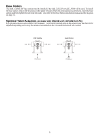
Two speed filter pump: Requires 2 relays (FILTER plus one of the AUX relays) for proper operation of both speeds. ! IMPORTANT: Be sure to follow the wiring diagram below AND to configure the control logic according to the Operation Instructions. Lights: A ground fault circuit breaker must be used to supply power for high voltage pool/spa lighting. Low voltage lights will require an external transformer. For lighting systems that have both a light source and color wheel, connect the light source to the "Lights" relay and then connect the color wheel to one of the AUX outputs. Hayward Variable Speed Filter Pump: Proper installation of the Hayward TriStar Variable Speed Control (VSC) includes high voltage input wiring, communication wiring, and menu configuration/settings. Refer to the following diagram for proper input wiring to the VSC. Wiring from a 240V breaker must connect through the OnCommand's Filter relay. The Filter relay is used to supply input power to the VSC pump control. The relay will be on when the filter pump output is on. When the filter pump output is off, the relay will be off. Note that when the filter pump relay is off (power off to the VSC), the OnCommand will not display errors or diagnostics for the pump. The filter pump relay must be on for diagnostic function. 240 VAC input power to VSC 7
-
 1
1 -
2
-
3
-
4
-
 5
5 -
 6
6 -
 7
7 -
 8
8 -
 9
9 -
 10
10 -
 11
11 -
 12
12 -
 13
13 -
 14
14 -
 15
15 -
16
-
17
-
18
-
19
-
20
-
21
-
22
-
23
-
24
-
25
-
26
-
27
-
28
-
29
-
30
-
31
-
32
 |
 |
