HP 3150 Service Manual - Page 119
Heating element
 |
UPC - 879889002135
View all HP 3150 manuals
Add to My Manuals
Save this manual to your list of manuals |
Page 119 highlights
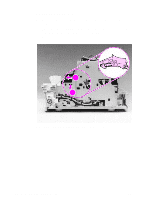
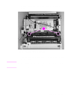
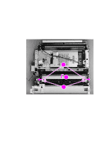
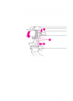
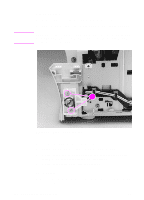
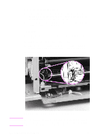
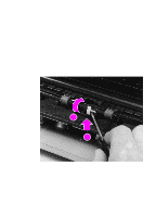
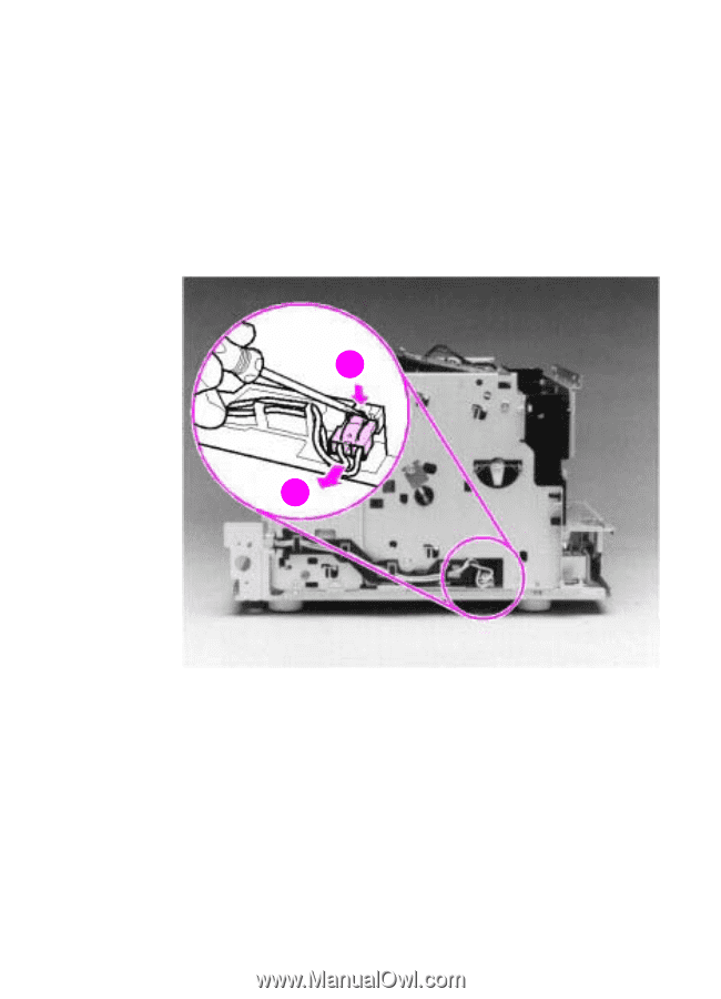
Heating element 1 Remove all covers, the RFI shield, the printer door, the exit roller, the delivery assembly, the fuser pressure plate, and the front casing. 2 Disconnect the AC voltage to the heating element by releasing the connector located on the ECU. Press down on the connector release with the small flatblade screwdriver (callout 1). (Because this is a small space, it is much easier to reach the connector with a screwdriver.) Pull the connector straight out (callout 2). 12 2 Figure 45. Heating element removal (1 of 2) 3 Remove the wire from the wire guides along the right side of the printer. EN Internal assemblies 117
-
 1
1 -
2
-
3
-
4
-
5
-
6
-
7
-
8
-
9
-
10
-
11
-
12
-
13
-
14
-
15
-
16
-
17
-
18
-
19
-
20
-
21
-
22
-
23
-
24
-
25
-
26
-
27
-
28
-
29
-
30
-
31
-
32
-
33
-
34
-
35
-
36
-
37
-
38
-
39
-
40
-
41
-
42
-
43
-
44
-
45
-
46
-
47
-
48
-
49
-
50
-
51
-
52
-
53
-
54
-
55
-
56
-
57
-
58
-
59
-
60
-
61
-
62
-
63
-
64
-
65
-
66
-
67
-
68
-
69
-
70
-
71
-
72
-
73
-
74
-
75
-
76
-
77
-
78
-
79
-
80
-
81
-
82
-
83
-
84
-
85
-
86
-
87
-
88
-
89
-
90
-
91
-
92
-
93
-
94
-
95
-
96
-
97
-
98
-
99
-
100
-
101
-
102
-
103
-
104
-
105
-
106
-
107
-
108
-
109
-
110
-
111
-
112
-
113
-
 114
114 -
 115
115 -
 116
116 -
 117
117 -
 118
118 -
 119
119 -
 120
120 -
 121
121 -
 122
122 -
 123
123 -
 124
124 -
125
-
126
-
127
-
128
-
129
-
130
-
131
-
132
-
133
-
134
-
135
-
136
-
137
-
138
-
139
-
140
-
141
-
142
-
143
-
144
-
145
-
146
-
147
-
148
-
149
-
150
-
151
-
152
-
153
-
154
-
155
-
156
-
157
-
158
-
159
-
160
-
161
-
162
-
163
-
164
-
165
-
166
-
167
-
168
-
169
-
170
-
171
-
172
-
173
-
174
-
175
-
176
-
177
-
178
-
179
-
180
-
181
-
182
-
183
-
184
-
185
-
186
-
187
-
188
-
189
-
190
-
191
-
192
-
193
-
194
-
195
-
196
-
197
-
198
-
199
-
200
-
201
-
202
-
203
-
204
-
205
-
206
-
207
-
208
-
209
-
210
-
211
-
212
-
213
-
214
-
215
-
216
-
217
-
218
-
219
-
220
-
221
-
222
-
223
-
224
-
225
-
226
-
227
-
228
-
229
-
230
-
231
-
232
-
233
-
234
-
235
-
236
-
237
-
238
-
239
-
240
-
241
-
242
-
243
-
244
-
245
-
246
-
247
-
248
-
249
-
250
-
251
-
252
-
253
-
254
-
255
-
256
-
257
-
258
-
259
-
260
-
261
-
262
-
263
-
264
-
265
-
266
-
267
-
268
-
269
-
270
-
271
-
272
 |
 |
EN
Internal assemblies
117
Heating element
1
Remove all covers, the RFI shield, the printer door, the exit roller,
the delivery assembly, the fuser pressure plate, and the front
casing.
2
Disconnect the AC voltage to the heating element by releasing
the connector located on the ECU. Press down on the connector
release with the small flatblade screwdriver (callout 1). (Because
this is a small space, it is much easier to reach the connector with
a screwdriver.) Pull the connector straight out (callout 2).
Figure 45.
Heating element removal (1 of 2)
3
Remove the wire from the wire guides along the right side of the
printer.
2
1
2
2