HP 3150 Service Manual - Page 129
pad and subpads order a separation pad and subpads under a single
 |
UPC - 879889002135
View all HP 3150 manuals
Add to My Manuals
Save this manual to your list of manuals |
Page 129 highlights
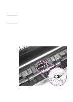
3 Using needlenose pliers, pull the bottom of the bushing out (callout 1), then turn it counterclockwise (callout 2) to release it. 2 12 Note Figure 55. Pickup roller assembly removal (2 of 2) 4 Lift the bushing out. 5 From inside the front of the printer, slide the right side of the pickup roller assembly forward, then lift the left side out. If you replace the pickup roller assembly, also replace the separation pad and subpads (order a separation pad and subpads under a single order number). See the removal procedures for the separation pad and subpads later in this chapter and also see Figure 96, "Paper pickup assembly," in Chapter 7. EN Internal assemblies 127
-
 1
1 -
2
-
3
-
4
-
5
-
6
-
7
-
8
-
9
-
10
-
11
-
12
-
13
-
14
-
15
-
16
-
17
-
18
-
19
-
20
-
21
-
22
-
23
-
24
-
25
-
26
-
27
-
28
-
29
-
30
-
31
-
32
-
33
-
34
-
35
-
36
-
37
-
38
-
39
-
40
-
41
-
42
-
43
-
44
-
45
-
46
-
47
-
48
-
49
-
50
-
51
-
52
-
53
-
54
-
55
-
56
-
57
-
58
-
59
-
60
-
61
-
62
-
63
-
64
-
65
-
66
-
67
-
68
-
69
-
70
-
71
-
72
-
73
-
74
-
75
-
76
-
77
-
78
-
79
-
80
-
81
-
82
-
83
-
84
-
85
-
86
-
87
-
88
-
89
-
90
-
91
-
92
-
93
-
94
-
95
-
96
-
97
-
98
-
99
-
100
-
101
-
102
-
103
-
104
-
105
-
106
-
107
-
108
-
109
-
110
-
111
-
112
-
113
-
114
-
115
-
116
-
117
-
118
-
119
-
120
-
121
-
122
-
123
-
 124
124 -
 125
125 -
 126
126 -
 127
127 -
 128
128 -
 129
129 -
 130
130 -
 131
131 -
 132
132 -
 133
133 -
 134
134 -
135
-
136
-
137
-
138
-
139
-
140
-
141
-
142
-
143
-
144
-
145
-
146
-
147
-
148
-
149
-
150
-
151
-
152
-
153
-
154
-
155
-
156
-
157
-
158
-
159
-
160
-
161
-
162
-
163
-
164
-
165
-
166
-
167
-
168
-
169
-
170
-
171
-
172
-
173
-
174
-
175
-
176
-
177
-
178
-
179
-
180
-
181
-
182
-
183
-
184
-
185
-
186
-
187
-
188
-
189
-
190
-
191
-
192
-
193
-
194
-
195
-
196
-
197
-
198
-
199
-
200
-
201
-
202
-
203
-
204
-
205
-
206
-
207
-
208
-
209
-
210
-
211
-
212
-
213
-
214
-
215
-
216
-
217
-
218
-
219
-
220
-
221
-
222
-
223
-
224
-
225
-
226
-
227
-
228
-
229
-
230
-
231
-
232
-
233
-
234
-
235
-
236
-
237
-
238
-
239
-
240
-
241
-
242
-
243
-
244
-
245
-
246
-
247
-
248
-
249
-
250
-
251
-
252
-
253
-
254
-
255
-
256
-
257
-
258
-
259
-
260
-
261
-
262
-
263
-
264
-
265
-
266
-
267
-
268
-
269
-
270
-
271
-
272
 |
 |

EN
Internal assemblies
127
3
Using needlenose pliers, pull the bottom of the bushing out
(callout 1), then turn it counterclockwise (callout 2) to release it.
Figure 55.
Pickup roller assembly removal (2 of 2)
4
Lift the bushing out.
5
From inside the front of the printer, slide the right side of the
pickup roller assembly forward, then lift the left side out.
Note
If you replace the pickup roller assembly, also replace the separation
pad and subpads (order a separation pad and subpads under a single
order number). See the removal procedures for the separation pad and
subpads later in this chapter and also see Figure 96, “Paper pickup
assembly,” in Chapter 7.
2
2
1
2