HP 4400 HP StorageWorks controller enclosure 4Gb array controller with embedde - Page 4
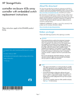
Verifying proper operation
 |
View all HP 4400 manuals
Add to My Manuals
Save this manual to your list of manuals |
Page 4 highlights
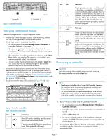
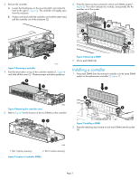
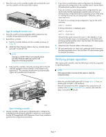
3. Place the cover on the controller module rails and slide the cover over the controller until the latch clicks in place. 15785 Figure 8 Installing the controller cover 4. Move the small form-factor pluggable (SFP) modules from the controller being replaced to the new controller. 5. Reinstall the controller. a. Push the controller halfway into the controller enclosure (1, Figure 9). b. Attach the Fibre Channel cables to the two controller device ports (DP1-A and DP1-B). NOTE: Inserting a controller without connecting the device port Fibre Channel cables may result in soft diagnostic errors being reported. c. Fully insert the controller. Move the mounting latch to the left until fully engaged and the controller is fully seated in the enclosure (2). The controller should power up automatically. Tighten the controller latch thumbscrew. 7. If you have a saved backup switch configuration file, download and restore the configuration to the controller switch. See the Fabric OS administrator guide for the procedure. If you do not have a saved backup switch configuration file, you should verify that the replacement controller does not have an existing zoning configuration before connecting servers to the array or inserting the array into an existing fabric. Otherwise, serious issues may occur. To check for an existing zoning configuration, log into the switch and enter: Swd77> cfgshow If zoning information is displayed, enter: Swd77> cfgclear Swd77> cfgdisable Check that the switch domain ID is set to 1 (the default) or, if you are connecting the array to an existing fabric, verify that the ID is not being used by another switch. See the Fabric OS administrator guide for the procedure. 8. Attach the Fibre Channel cables to the switch ports. 9. HP recommends that you check and update the switch firmware to the latest supported version. See the Fabric OS administrator guide for detailed procedures. Verifying proper operation After replacing the controller, check the following to verify the component is operating properly: NOTE: Wait approximately 3 minutes for the system to check the component status. • Verify the controller health green LED is lit (see Table 1). If not, try reseating the controller in the enclosure. • From HP Command View EVA, navigate to the component as described in the Verifying component failure section, and check the status. It should be (Good). 2 1 15786 Figure 9 Installing a controller 6. Use the controller console port (or Ethernet port) to configure the embedded switch settings to establish a connection to your network. See the HP StorageWorks 4400 Enterprise Virtual Array installation guide for the configuration procedures. Page 4
-
 1
1 -
 2
2 -
 3
3 -
 4
4
 |
 |
