HP AP775A Cisco MDS 9500 Series Hardware Installation Guide (OL-17467-02, Octo - Page 135
AC Power Supply for the Cisco MDS 9513 Director, Step 4
 |
UPC - 884962062708
View all HP AP775A manuals
Add to My Manuals
Save this manual to your list of manuals |
Page 135 highlights
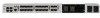
Chapter 2 Installing the Cisco MDS 9500 Series Removing and Installing a Power Supply or PEM Send documentation comments to [email protected]. Figure 2-29 AC Power Supply for the Cisco MDS 9513 Director 1 144528 2 2 1 Power supply switch 2 Power cable retainer Step 4 Grasp the power supply handles, one with each hand. Orient the power supply and align it with the bay. Note There is a handle at the top rear of the power supply you can also use to tilt the power supply into the bay. Step 5 Step 6 Step 7 Step 8 Step 9 Step 10 Slide the power supply into the power supply bay. Ensure that the power supply is fully seated in the bay. Secure all four 6-32 panel fasteners and tighten to 8 in-lbs. Plug the power cable into the power supply, and tighten the screw on the cable retention device to ensure that the cable cannot be pulled out. Connect the other end of the power cable to an AC power source. Turn the power switch to the on (|) position on the power supply. Verify power supply operation by checking that the power supply LEDs are in the following states: • INPUT OK LEDs are green. • FANs OK LED is green. • OUTPUT FAIL LED is off. OL-17467-02 Cisco MDS 9500 Series Hardware Installation Guide 2-55
-
 1
1 -
2
-
3
-
4
-
5
-
6
-
7
-
8
-
9
-
10
-
11
-
12
-
13
-
14
-
15
-
16
-
17
-
18
-
19
-
20
-
21
-
22
-
23
-
24
-
25
-
26
-
27
-
28
-
29
-
30
-
31
-
32
-
33
-
34
-
35
-
36
-
37
-
38
-
39
-
40
-
41
-
42
-
43
-
44
-
45
-
46
-
47
-
48
-
49
-
50
-
51
-
52
-
53
-
54
-
55
-
56
-
57
-
58
-
59
-
60
-
61
-
62
-
63
-
64
-
65
-
66
-
67
-
68
-
69
-
70
-
71
-
72
-
73
-
74
-
75
-
76
-
77
-
78
-
79
-
80
-
81
-
82
-
83
-
84
-
85
-
86
-
87
-
88
-
89
-
90
-
91
-
92
-
93
-
94
-
95
-
96
-
97
-
98
-
99
-
100
-
101
-
102
-
103
-
104
-
105
-
106
-
107
-
108
-
109
-
110
-
111
-
112
-
113
-
114
-
115
-
116
-
117
-
118
-
119
-
120
-
121
-
122
-
123
-
124
-
125
-
126
-
127
-
128
-
129
-
 130
130 -
 131
131 -
 132
132 -
 133
133 -
 134
134 -
 135
135 -
 136
136 -
 137
137 -
 138
138 -
 139
139 -
 140
140 -
141
-
142
-
143
-
144
-
145
-
146
-
147
-
148
-
149
-
150
-
151
-
152
-
153
-
154
-
155
-
156
-
157
-
158
-
159
-
160
-
161
-
162
-
163
-
164
-
165
-
166
-
167
-
168
-
169
-
170
-
171
-
172
-
173
-
174
-
175
-
176
-
177
-
178
-
179
-
180
-
181
-
182
-
183
-
184
-
185
-
186
-
187
-
188
-
189
-
190
-
191
-
192
-
193
-
194
-
195
-
196
-
197
-
198
-
199
-
200
-
201
-
202
-
203
-
204
-
205
-
206
-
207
-
208
-
209
-
210
-
211
-
212
-
213
-
214
-
215
-
216
-
217
-
218
-
219
-
220
-
221
-
222
-
223
-
224
-
225
-
226
-
227
-
228
-
229
-
230
-
231
-
232
-
233
-
234
-
235
-
236
-
237
-
238
-
239
-
240
-
241
-
242
-
243
-
244
-
245
-
246
-
247
-
248
-
249
-
250
-
251
-
252
-
253
-
254
-
255
-
256
-
257
-
258
-
259
-
260
-
261
-
262
-
263
-
264
-
265
-
266
-
267
-
268
-
269
-
270
-
271
-
272
-
273
-
274
-
275
-
276
-
277
-
278
-
279
-
280
-
281
-
282
-
283
-
284
-
285
-
286
-
287
-
288
 |
 |
