HP AP775A Cisco Nexus 5000 Series Hardware Installation Guide (OL-15902-01, No - Page 62
Removing and Installing Components
 |
UPC - 884962062708
View all HP AP775A manuals
Add to My Manuals
Save this manual to your list of manuals |
Page 62 highlights
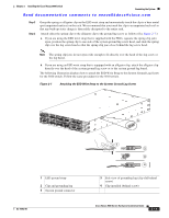
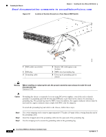
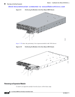
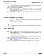
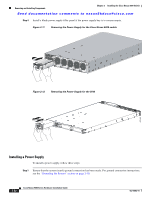
Removing and Installing Components Chapter 2 Installing the Cisco Nexus 5000 Switch Send documentation comments to [email protected] Step 6 After the switch boots, verify that the LED operation is as follows: • Fan module-Status LED is green. • Power supply-Status LED is green. • After initialization, the system status LED is green, indicating that all chassis environmental monitors are reporting that the system is operational. If this LED is orange or red, then one or more environmental monitor is reporting a problem. • The Link LEDs for the Ethernet connector should not be on unless the cable is connected. Note The link LEDs for the Fibre Channel ports remain yellow until the ports are enabled, and the LED for the Ethernet connector port remains off until the port is connected. Step 7 Try removing and reinstalling a component that is not operating correctly. If it still does not operate correctly, contact your customer service representative for a replacement. Note If you purchased this product through a Cisco reseller, contact the reseller directly for technical support. If you purchased this product directly from Cisco, contact Cisco Technical Support at this URL: http://www.cisco.com/warp/public/687/Directory/DirTAC.shtml. Step 8 Step 9 Verify that the system software has booted and the switch has initialized without error messages. If any problems occur, see Appendix E, "Troubleshooting Hardware Components". If you cannot resolve an issue, contact your customer service representative. Complete the worksheets provided in Appendix D, "Site Planning and Maintenance Records" for future reference. Note A setup utility automatically launches the first time you access the switch and guides you through the basic configuration. For instructions on how to configure the switch and check module connectivity, see the Cisco Nexus 5000 Series CLI Configuration Guide or the Cisco Nexus 5000 Series Fabric Manager Configuration Guide. Removing and Installing Components This section includes the following topics: • Removing and Installing Expansion Modules, page 2-19 • Removing and Installing Power Supplies, page 2-21 • Removing and Installing the Fan Module, page 2-23 • Removing the Cisco Nexus 5000 Switch, page 2-25 Caution To prevent ESD damage, wear grounding wrist straps during these procedures and handle modules by the carrier edges only. 2-18 Cisco Nexus 5000 Series Hardware Installation Guide OL-15902-01
-
 1
1 -
2
-
3
-
4
-
5
-
6
-
7
-
8
-
9
-
10
-
11
-
12
-
13
-
14
-
15
-
16
-
17
-
18
-
19
-
20
-
21
-
22
-
23
-
24
-
25
-
26
-
27
-
28
-
29
-
30
-
31
-
32
-
33
-
34
-
35
-
36
-
37
-
38
-
39
-
40
-
41
-
42
-
43
-
44
-
45
-
46
-
47
-
48
-
49
-
50
-
51
-
52
-
53
-
54
-
55
-
56
-
 57
57 -
 58
58 -
 59
59 -
 60
60 -
 61
61 -
 62
62 -
 63
63 -
 64
64 -
 65
65 -
 66
66 -
 67
67 -
68
-
69
-
70
-
71
-
72
-
73
-
74
-
75
-
76
-
77
-
78
-
79
-
80
-
81
-
82
-
83
-
84
-
85
-
86
-
87
-
88
-
89
-
90
-
91
-
92
-
93
-
94
-
95
-
96
-
97
-
98
-
99
-
100
-
101
-
102
-
103
-
104
-
105
-
106
-
107
-
108
-
109
-
110
-
111
-
112
 |
 |
