HP Cisco MDS 9120 Cisco MDS 9100 Series Hardware Installation Guide (OL-17951- - Page 46
Installing the Notched Slider Rails to the Front Rack-Mounting Rails
 |
View all HP Cisco MDS 9120 manuals
Add to My Manuals
Save this manual to your list of manuals |
Page 46 highlights
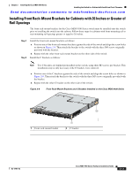
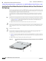
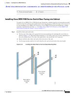
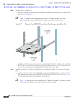
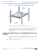
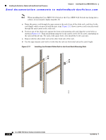
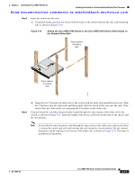
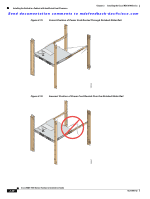
Installing the Switch in a Cabinet with Insufficient Front Clearance Chapter 2 Installing the Cisco MDS 9100 Series Send documentation comments to [email protected] Note When installing the Cisco MDS 9134 Switch or the Cisco MDS 9124 Switch rear-facing into a cabinet, do not install it higher than RU-30. a. Route the power cord through the open cutout at the end of one of the slider rails, and then let the cord dangle while you proceed with the next steps. Figure 2-15 shows a power cord correctly routed through the open cutout in the slider rail. b. Position one of the slider rails against the front rack-mounting rails and align the screw holes as shown in Figure 2-13. Then attach them using two 12-24 screws or two 10-32 screws, depending on the rack rail thread type. For racks with square holes, first install the 12-24 cage nuts. c. Repeat with the other slider rail on the other front side of the rack. d. Use the tape measure and level to verify that the rails are horizontal and at the same height. Figure 2-13 Installing the Notched Slider Rails to the Front Rack-Mounting Rails 182462 2-18 Cisco MDS 9100 Series Hardware Installation Guide OL-17951-02
-
 1
1 -
2
-
3
-
4
-
5
-
6
-
7
-
8
-
9
-
10
-
11
-
12
-
13
-
14
-
15
-
16
-
17
-
18
-
19
-
20
-
21
-
22
-
23
-
24
-
25
-
26
-
27
-
28
-
29
-
30
-
31
-
32
-
33
-
34
-
35
-
36
-
37
-
38
-
39
-
40
-
 41
41 -
 42
42 -
 43
43 -
 44
44 -
 45
45 -
 46
46 -
 47
47 -
 48
48 -
 49
49 -
 50
50 -
 51
51 -
52
-
53
-
54
-
55
-
56
-
57
-
58
-
59
-
60
-
61
-
62
-
63
-
64
-
65
-
66
-
67
-
68
-
69
-
70
-
71
-
72
-
73
-
74
-
75
-
76
-
77
-
78
-
79
-
80
-
81
-
82
-
83
-
84
-
85
-
86
-
87
-
88
-
89
-
90
-
91
-
92
-
93
-
94
-
95
-
96
-
97
-
98
-
99
-
100
-
101
-
102
-
103
-
104
-
105
-
106
-
107
-
108
 |
 |
