HP Cisco MDS 9120 Cisco MDS 9100 Series Hardware Installation Guide (OL-17951- - Page 98
Supported Power Cords and Plugs, Power Cords
 |
View all HP Cisco MDS 9120 manuals
Add to My Manuals
Save this manual to your list of manuals |
Page 98 highlights
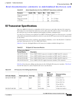
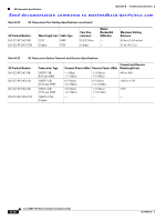
Supported Power Cords and Plugs Appendix C Cable and Port Specifications Send documentation comments to [email protected] Table C-4 lists the connector pinouts and signal names for a 10/100BASE-T management port (MDI) cable. Table C-4 10/100BASE-T Management Port Cable Pinout Pin Signal 1 TD+ 2 TD- 3 RD+ 6 RD- 4 Not used 5 Not used 7 Not used 8 Not used Figure C-2 shows a schematic of the 10/100BASE-T cable. Figure C-2 Switch 1 RD+ 2 RD3 TD+ 6 TD- Twisted-Pair 10/100BASE-T Cable Schematic Switch 1 RD+ 2 RD3 TD+ 6 TD- 4 NC 5 NC 7 NC 8 NC 4 NC 5 NC 7 NC 8 NC 65273 Supported Power Cords and Plugs A separate power cord is provided for each power supply. Standard power cords or jumper power cords are available for connection to a power distribution unit having IEC 60320 C13 outlet receptacles. The jumper power cords, for use in cabinets, are available as an option instead of the standard power cords. Power Cords The standard power cords have an IEC C15 connector on the end that plugs into the switch. The optional jumper power cords have an IEC C15 connector on the end that plugs into the switch, and an IEC C14 connector on the end that plugs into an IEC C13 outlet receptacle. Note Only the standard power cords or jumper power cords provided with the switch are supported. Cisco MDS 9100 Series Hardware Installation Guide C-4 OL-17951-02
-
 1
1 -
2
-
3
-
4
-
5
-
6
-
7
-
8
-
9
-
10
-
11
-
12
-
13
-
14
-
15
-
16
-
17
-
18
-
19
-
20
-
21
-
22
-
23
-
24
-
25
-
26
-
27
-
28
-
29
-
30
-
31
-
32
-
33
-
34
-
35
-
36
-
37
-
38
-
39
-
40
-
41
-
42
-
43
-
44
-
45
-
46
-
47
-
48
-
49
-
50
-
51
-
52
-
53
-
54
-
55
-
56
-
57
-
58
-
59
-
60
-
61
-
62
-
63
-
64
-
65
-
66
-
67
-
68
-
69
-
70
-
71
-
72
-
73
-
74
-
75
-
76
-
77
-
78
-
79
-
80
-
81
-
82
-
83
-
84
-
85
-
86
-
87
-
88
-
89
-
90
-
91
-
92
-
 93
93 -
 94
94 -
 95
95 -
 96
96 -
 97
97 -
 98
98 -
 99
99 -
 100
100 -
 101
101 -
 102
102 -
 103
103 -
104
-
105
-
106
-
107
-
108
 |
 |
