HP Cisco MDS 9120 Cisco MDS 9124e Fabric Switch for HP c-Class BladeSystem Use - Page 13
Port side of the Switch, Internal ports summary, Switch redundancy
 |
View all HP Cisco MDS 9120 manuals
Add to My Manuals
Save this manual to your list of manuals |
Page 13 highlights
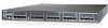
Port side of the Switch Figure 2 and Table 3 identify Cisco MDS 9124e Fabric Switch external ports (ports EXT 1 through EXT 4 and ports EXT 5 through EXT 8). 181735 EXT 1 EXT 2 EXT 3 EXT 4 ! LiNK EXT 5 EXT 6 EXT 7 EXT 8 Cisco MDS 9124e 1 2 Figure 2 Cisco MDS 9124e Fabric Switch external ports Table 3 Identifying Cisco MDS 9124e Fabric Switch external ports Item Description 1 Left bank - EXT 1, EXT 2, EXT 3 and EXT 4 2 Right bank - EXT 5, EXT 6, EXT 7 and EXT 8 NOTE: Refer to Interpreting LED activity for complete information on switch LEDs. Internal ports summary Sixteen logical internal ports (numbered 1 through 16) connect sequentially to server bays 1 through 16 via the enclosure midplane. Server bay 1 is connected to Switch Port 1, Server bay 2 is connected to Switch port 2, and so forth. Switch redundancy The HP c-Class BladeSystem was engineered as a no-single-point-of-failure bladed solution. Attributes that contribute to switch redundancy include: • Redundant power and cooling • Redundant HP Onboard Administrator (OA) to ensure management access to the switch NOTE: The HP Onboard Administrator is the enclosure management module used to support and manage the HP c-Class BladeSystem and all managed devices used in the enclosure. Cisco MDS 9124e Fabric Switch for HP c-Class BladeSystem 13
-
 1
1 -
2
-
3
-
4
-
5
-
6
-
7
-
 8
8 -
 9
9 -
 10
10 -
 11
11 -
 12
12 -
 13
13 -
 14
14 -
 15
15 -
 16
16 -
 17
17 -
 18
18 -
19
-
20
-
21
-
22
-
23
-
24
-
25
-
26
-
27
-
28
-
29
-
30
-
31
-
32
-
33
-
34
-
35
-
36
-
37
-
38
-
39
-
40
-
41
-
42
-
43
-
44
-
45
-
46
-
47
-
48
-
49
-
50
-
51
-
52
-
53
-
54
-
55
-
56
-
57
-
58
-
59
-
60
-
61
-
62
-
63
-
64
-
65
-
66
-
67
-
68
 |
 |
