HP Cisco MDS 9124 Cisco MDS 9500 Series Hardware Installation Guide (OL-17467- - Page 157
Removing a Clock Module from the Cisco MDS 9513 Director
 |
View all HP Cisco MDS 9124 manuals
Add to My Manuals
Save this manual to your list of manuals |
Page 157 highlights
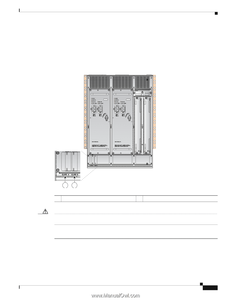
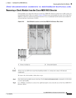
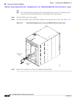
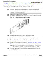
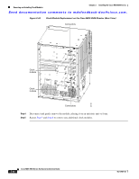
Chapter 2 Installing the Cisco MDS 9500 Series Removing and Installing Clock Modules Send documentation comments to [email protected]. Removing a Clock Module from the Cisco MDS 9513 Director Clock modules are connected to the rear of the Cisco MDS 9513 Director and are not visible as they are located on the inside of the cover panel. Figure 2-40 shows the clock modules in a rear view of the Cisco MDS 9513 Director with the back panel removed. Cisco recommends that the failed clock module be replaced during a maintenance window. Figure 2-40 Clock Module Location on the Cisco MDS 9513 Director (Rear View) 144601 12 1 Clock A (CLK A) 2 Clock B (CLK B) Caution Always wear an ESD wrist strap when handling modules or coming into contact with internal components. To remove the clock module, follow these steps: Step 1 Step 2 Note which clock module you are removing. Use the show environment clock command to verify which is active and standby. Use a Phillips screwdriver to remove the eight back panel screws from the rear of the Cisco MDS 9513 Director chassis. OL-17467-02 Cisco MDS 9500 Series Hardware Installation Guide 2-77
-
 1
1 -
2
-
3
-
4
-
5
-
6
-
7
-
8
-
9
-
10
-
11
-
12
-
13
-
14
-
15
-
16
-
17
-
18
-
19
-
20
-
21
-
22
-
23
-
24
-
25
-
26
-
27
-
28
-
29
-
30
-
31
-
32
-
33
-
34
-
35
-
36
-
37
-
38
-
39
-
40
-
41
-
42
-
43
-
44
-
45
-
46
-
47
-
48
-
49
-
50
-
51
-
52
-
53
-
54
-
55
-
56
-
57
-
58
-
59
-
60
-
61
-
62
-
63
-
64
-
65
-
66
-
67
-
68
-
69
-
70
-
71
-
72
-
73
-
74
-
75
-
76
-
77
-
78
-
79
-
80
-
81
-
82
-
83
-
84
-
85
-
86
-
87
-
88
-
89
-
90
-
91
-
92
-
93
-
94
-
95
-
96
-
97
-
98
-
99
-
100
-
101
-
102
-
103
-
104
-
105
-
106
-
107
-
108
-
109
-
110
-
111
-
112
-
113
-
114
-
115
-
116
-
117
-
118
-
119
-
120
-
121
-
122
-
123
-
124
-
125
-
126
-
127
-
128
-
129
-
130
-
131
-
132
-
133
-
134
-
135
-
136
-
137
-
138
-
139
-
140
-
141
-
142
-
143
-
144
-
145
-
146
-
147
-
148
-
149
-
150
-
151
-
 152
152 -
 153
153 -
 154
154 -
 155
155 -
 156
156 -
 157
157 -
 158
158 -
 159
159 -
 160
160 -
 161
161 -
 162
162 -
163
-
164
-
165
-
166
-
167
-
168
-
169
-
170
-
171
-
172
-
173
-
174
-
175
-
176
-
177
-
178
-
179
-
180
-
181
-
182
-
183
-
184
-
185
-
186
-
187
-
188
-
189
-
190
-
191
-
192
-
193
-
194
-
195
-
196
-
197
-
198
-
199
-
200
-
201
-
202
-
203
-
204
-
205
-
206
-
207
-
208
-
209
-
210
-
211
-
212
-
213
-
214
-
215
-
216
-
217
-
218
-
219
-
220
-
221
-
222
-
223
-
224
-
225
-
226
-
227
-
228
-
229
-
230
-
231
-
232
-
233
-
234
-
235
-
236
-
237
-
238
-
239
-
240
-
241
-
242
-
243
-
244
-
245
-
246
-
247
-
248
-
249
-
250
-
251
-
252
-
253
-
254
-
255
-
256
-
257
-
258
-
259
-
260
-
261
-
262
-
263
-
264
-
265
-
266
-
267
-
268
-
269
-
270
-
271
-
272
-
273
-
274
-
275
-
276
-
277
-
278
-
279
-
280
-
281
-
282
-
283
-
284
-
285
-
286
-
287
-
288
 |
 |