HP Cisco MDS 9222i Cisco MDS 9200 Series Hardware Installation Guide (OL-16188 - Page 88
Removing Other Switching or Services Modules, Cisco MDS 9000 Family CLI Configuration Guide
 |
View all HP Cisco MDS 9222i manuals
Add to My Manuals
Save this manual to your list of manuals |
Page 88 highlights
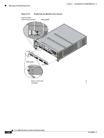
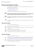
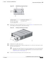
Removing and Installing Components Chapter 2 Installing the Cisco MDS 9200 Series To remove a CSM module from the chassis, follow these steps: Step 1 Step 2 Step 3 Step 4 Step 5 Step 6 Power off the module from the CLI. For information about the correct command to use, see the Cisco MDS 9000 Family CLI Configuration Guide. Ensure that the backup process has completed by verifying that all LEDs on the module have turned off. This requires up to 10 minutes. Loosen the two captive screws on the module. Remove the module from the chassis as follows: a. Place your thumbs on the left and right ejector levers (shown in Figure 2-18 on page 2-30) and simultaneously rotate the levers outward to unseat the module from the backplane connector. b. Grasp the front edge of the module and slide the module part of the way out of the slot. Place your other hand under the module to support the weight of the module. Do not touch the module circuitry. Place the module on an antistatic mat or antistatic foam if not immediately reinstalling it in another slot. Install a filler panel to keep dust out of the chassis and maintain consistent airflow if the slot will remain empty. Warning Blank faceplates and cover panels serve three important functions: they prevent exposure to hazardous voltages and currents inside the chassis; they contain electromagnetic interference (EMI) that might disrupt other equipment; and they direct the flow of cooling air through the chassis. Do not operate the system unless all cards, faceplates, front covers, and rear covers are in place. Statement 1029 Removing Other Switching or Services Modules To remove a switching or services module from the chassis, follow these steps: Step 1 Step 2 Step 3 Step 4 Step 5 Disconnect any network interface cables attached to the module. Loosen the two captive screws on the module. Remove the module from the chassis as follows: a. Place your thumbs on the left and right ejector levers (shown in Figure 2-18 on page 2-30) and simultaneously rotate the levers outward to unseat the module from the backplane connector. b. Grasp the front edge of the module and slide the module part of the way out of the slot. Place your other hand under the module to support the weight of the module. Do not touch the module circuitry. Place the module on an antistatic mat or antistatic foam if not immediately reinstalling it in another slot. Install a filler panel to keep dust out of the chassis and maintain consistent airflow if the slot will remain empty. 2-32 Cisco MDS 9200 Series Hardware Installation Guide OL-16188-01
-
 1
1 -
2
-
3
-
4
-
5
-
6
-
7
-
8
-
9
-
10
-
11
-
12
-
13
-
14
-
15
-
16
-
17
-
18
-
19
-
20
-
21
-
22
-
23
-
24
-
25
-
26
-
27
-
28
-
29
-
30
-
31
-
32
-
33
-
34
-
35
-
36
-
37
-
38
-
39
-
40
-
41
-
42
-
43
-
44
-
45
-
46
-
47
-
48
-
49
-
50
-
51
-
52
-
53
-
54
-
55
-
56
-
57
-
58
-
59
-
60
-
61
-
62
-
63
-
64
-
65
-
66
-
67
-
68
-
69
-
70
-
71
-
72
-
73
-
74
-
75
-
76
-
77
-
78
-
79
-
80
-
81
-
82
-
 83
83 -
 84
84 -
 85
85 -
 86
86 -
 87
87 -
 88
88 -
 89
89 -
 90
90 -
 91
91 -
 92
92 -
 93
93 -
94
-
95
-
96
-
97
-
98
-
99
-
100
-
101
-
102
-
103
-
104
-
105
-
106
-
107
-
108
-
109
-
110
-
111
-
112
-
113
-
114
-
115
-
116
-
117
-
118
-
119
-
120
-
121
-
122
-
123
-
124
-
125
-
126
-
127
-
128
-
129
-
130
-
131
-
132
-
133
-
134
-
135
-
136
-
137
-
138
-
139
-
140
-
141
-
142
-
143
-
144
-
145
-
146
-
147
-
148
-
149
-
150
-
151
-
152
-
153
-
154
-
155
-
156
-
157
-
158
-
159
-
160
-
161
-
162
-
163
-
164
 |
 |
