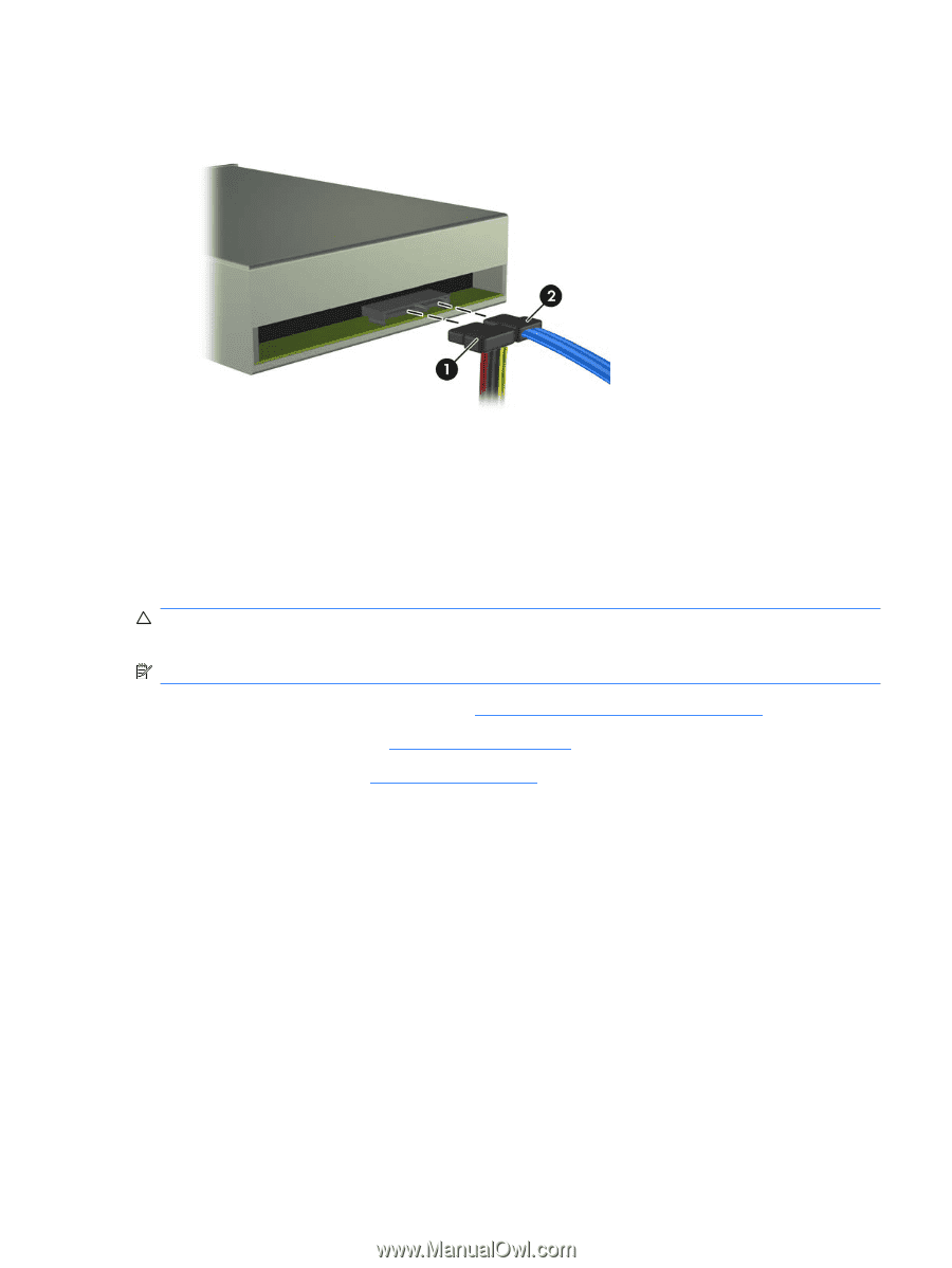
HP Dx7500 Service Reference Guide: HP Compaq dx7500 Business PC - Page 115
Removing an External 3.5-inch Drive, Remove the front bezel
 |
UPC - 884420980605
View all HP Dx7500 manuals
Add to My Manuals
Save this manual to your list of manuals |
Page 115 highlights
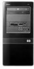
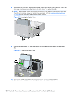
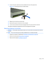
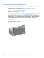
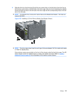
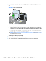
11. Connect the power cable (1) and data cable (2) to the rear of the optical drive. Figure 8-14 Connecting the Power and Data Cables 12. Replace the front bezel and access panel. 13. Reconnect the power cord and turn on the computer. 14. Lock any security devices that were disengaged when the access panel was removed. The system automatically recognizes the drive and reconfigures the computer. Removing an External 3.5-inch Drive CAUTION: All removable media should be taken out of a drive before removing the drive from the computer. NOTE: The 3.5-inch drive bay may contain a diskette drive or a media card reader. 1. Prepare the computer for disassembly (Preparation for Disassembly on page 91). 2. Remove the access panel (Access Panel on page 92). 3. Remove the front bezel (Front Bezel on page 93). Drives 105
-
 1
1 -
2
-
3
-
4
-
5
-
6
-
7
-
8
-
9
-
10
-
11
-
12
-
13
-
14
-
15
-
16
-
17
-
18
-
19
-
20
-
21
-
22
-
23
-
24
-
25
-
26
-
27
-
28
-
29
-
30
-
31
-
32
-
33
-
34
-
35
-
36
-
37
-
38
-
39
-
40
-
41
-
42
-
43
-
44
-
45
-
46
-
47
-
48
-
49
-
50
-
51
-
52
-
53
-
54
-
55
-
56
-
57
-
58
-
59
-
60
-
61
-
62
-
63
-
64
-
65
-
66
-
67
-
68
-
69
-
70
-
71
-
72
-
73
-
74
-
75
-
76
-
77
-
78
-
79
-
80
-
81
-
82
-
83
-
84
-
85
-
86
-
87
-
88
-
89
-
90
-
91
-
92
-
93
-
94
-
95
-
96
-
97
-
98
-
99
-
100
-
101
-
102
-
103
-
104
-
105
-
106
-
107
-
108
-
109
-
 110
110 -
 111
111 -
 112
112 -
 113
113 -
 114
114 -
 115
115 -
 116
116 -
 117
117 -
 118
118 -
 119
119 -
 120
120 -
121
-
122
-
123
-
124
-
125
-
126
-
127
-
128
-
129
-
130
-
131
-
132
-
133
-
134
-
135
-
136
-
137
-
138
-
139
-
140
-
141
-
142
-
143
-
144
-
145
-
146
-
147
-
148
-
149
-
150
-
151
-
152
-
153
-
154
-
155
-
156
-
157
-
158
-
159
-
160
-
161
-
162
-
163
-
164
-
165
-
166
-
167
-
168
-
169
-
170
-
171
-
172
-
173
-
174
-
175
-
176
-
177
-
178
-
179
-
180
-
181
-
182
-
183
-
184
-
185
-
186
-
187
-
188
-
189
-
190
-
191
-
192
-
193
-
194
-
195
-
196
-
197
-
198
-
199
-
200
 |
 |