HP E24m Maintenance and Service Guide
HP E24m Manual
 |
View all HP E24m manuals
Add to My Manuals
Save this manual to your list of manuals |
HP E24m manual content summary:
- HP E24m | Maintenance and Service Guide - Page 1
Maintenance and Service Guide E24m G4 model SUMMARY This guide provides information about spare parts, removal and replacement of parts, diagnostic tests, problem troubleshooting, and more. - HP E24m | Maintenance and Service Guide - Page 2
statements accompanying such products and services. Nothing herein should be construed as constituting an additional warranty. HP shall not be liable for technical or editorial errors or omissions contained herein. First Edition: October 2021 Document Part Number: M56185-E24m G4-MSG-V1 Assembly part - HP E24m | Maintenance and Service Guide - Page 3
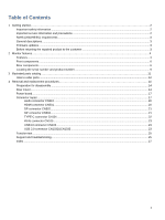
Table of Contents 1 Getting started...2 Important safety information ...2 Important service information and precautions...2 RoHS (2002/95/EC) requirements ...3 General descriptions CN103 ...23 USB 3.0 connector CN1032&CN1033 ...23 Function test ...25 Support and troubleshooting...25 Index ...27 1 - HP E24m | Maintenance and Service Guide - Page 4
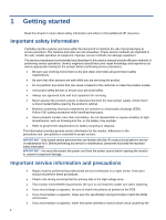
to the safe, reliable operation of equipment. Improper service methods can damage equipment. The service procedures recommended and described in this service manual provide effective methods of performing service operations. Service engineers should have prior repair knowledge and experience as - HP E24m | Maintenance and Service Guide - Page 5
replacement. General descriptions This manual contains general information. There are two levels of service: Level 1: Cosmetic/appearance/alignment service Level 2: Circuit board or standard parts replacement Firmware updates Firmware updates for the monitor are available at support.hp.com. If no - HP E24m | Maintenance and Service Guide - Page 6
provides network, data, video and power delivery(up to 65w) ● Plug and Play capability, if supported by your operating system Monitor stand ● Removable stand for flexible monitor head mounting solutions ● HP Quick Release 2 device to quickly attach the monitor head to the stand with a simple click - HP E24m | Maintenance and Service Guide - Page 7
to a swing arm mount NOTE: For safety and regulatory information, refer to the Product Notices provided in your documentation kit. To access the latest user guides or manuals for your product, go to http://www.hp.com/support and follow the instructions to find your product. Then select - HP E24m | Maintenance and Service Guide - Page 8
Front components To identify the components on the front of the monitor, use this illustration and table. Table 1-1: Front components and their descriptions Component 1 Camera 2 Speaker mute light 3 Speaker mute button 4 Speaker button (decrease sound) 5 Speaker button (increase sound) 6 Microphone - HP E24m | Maintenance and Service Guide - Page 9
audio cable. Also connects an optional headset microphone. This jack does not support optional standalone microphones. IMPORTANT: To reduce the risk of personal injury, Regulatory, Safety, and Environmental Notices To access this guide, type HP Documentation in the taskbar search box, and then select - HP E24m | Maintenance and Service Guide - Page 10
Type C cable from the source device to the monitor. Serves as a single connection when docking an HP notebook. Connects a DisplayPort cable from the monitor to a secondary monitor. Connects an RJ-45 Ethernet . Connect USB devices to the monitor NOTE: The upper port supports USB battery charging. 8 - HP E24m | Maintenance and Service Guide - Page 11
located on the rear of the monitor. The serial number and product number are located on a Safety label. You may need these numbers when contacting HP about the monitor model. For worldwide models (except India): Barcode label Spec label For India: Bar code label 9 - HP E24m | Maintenance and Service Guide - Page 12
Spec label 10 - HP E24m | Maintenance and Service Guide - Page 13
parts catalog To identify the monitor major components, use this illustration and table. Item 1 2 3 4 5 6 7 8 9 10 11 12 13 14 Description LOGO HP 12 DECO_BEZEL Deco mylar Speaker Cover Lens SPEAKER Panel MIDDLE_FRAME INSULATING SHEET Power Board RUBBER PAD MAINFRAME HEAT SINK Skype key board Qty - HP E24m | Maintenance and Service Guide - Page 14
1 S4 0M1G102500404700RA 1 S5 QM1G074Z1002250AH1 4 How to order parts The HP authorized repair center can purchase the power board from HP. Power board Description PSU E24m G4 1st source PSU E24m G4 2nd source HP spare part number M74290-001 M74290-002 Manufacturer part number PLPCD561KAAG - HP E24m | Maintenance and Service Guide - Page 15
: EET https://www.eetgroup.com/en-eu/ NOTE: HP continually improves and changes product parts. For complete and current information about supported parts for your product, go to https://partsurfer.hp.com/Search.aspx, select your country or region, and then follow the on-screen instructions. 13 - HP E24m | Maintenance and Service Guide - Page 16
prepare to disassemble and reassemble the monitor. 1) Read the "Important safety information" and "Important service information and precautions" sections in the "Getting started" chapter of this guide. 2) Clean the room for disassembly. 3) Identify the disassembly area. 4) Check the position that - HP E24m | Maintenance and Service Guide - Page 17
1) Remove four screw from the rear case. 2) Use your fingers to split the left and right sides apart between the middle frame and rear case. 3) Insert the scraper bar tool into the gap between the middle frame and rear case, and then rotate. The hook opens. Repeat the steps. 4) Disassemble Rear - HP E24m | Maintenance and Service Guide - Page 18
6) Remove the Audio board wire, Connector board wire and Webcam module wire from the Interfaceboard. 7) Disassemble the USB board from the Rear Cover (if required). 8) Remove 2 screws from the bracket. 9) Disassemble 7 screws from the board. 10) Disassemble all the boards from housing. 11) - HP E24m | Maintenance and Service Guide - Page 19
board, follow these steps: ▲ Prepare the monitor for disassembly. See Preparation for disassembly on page 14. Remove the power board: 1) The HP E24m G4 power board connector position is as follows: CN801 CN910 1 Warning: After unplugging the power supply, the capacitance is still charged, do not - HP E24m | Maintenance and Service Guide - Page 20
The connectors are on the main board (board part number CBPCPD9H1Q1) The connectors identifiers are as follows: Connector HDMI DisplayPort 1 DisplayPort 2 USB Type-C RJ45 USB 3.0 Location CN501 CN502 CN503 CN101 CN105 CN103 MAIN BOARD CN501 CN502 CN101 CN503 CN105 CN103 This procedure includes - HP E24m | Maintenance and Service Guide - Page 21
AUDIO BOARD CN610 This procedure includes USB3.0 connectors The connectors is on USB board (board part number USBPQAE). The connector identifiers are as follows: Connector USB 3.0 USB 3.0 Location CN1032 CN1033 USB BOARD CN1033 CN1032 Before repairing connectors, follow these steps: ▲ - HP E24m | Maintenance and Service Guide - Page 22
• If connector need to replace, please insert new parts carefully because the near pin may cause short circuit by inappropriate operate. • DO NOT allow any liquid on the board. Water and moisture may cause short-circuit to the electronic components and lead to malfunctions. • The fusion point of - HP E24m | Maintenance and Service Guide - Page 23
2) Use a hot air gun to melt the solder on the pins. 3) Lift the CN501 connector from the circuit board. 4) Place the new component on the circuit board. Be sure that it matches the footprint. 5) Solder the new component. DP connector CN502 Repair the DP connector: 1) Use a soldering iron and a de- - HP E24m | Maintenance and Service Guide - Page 24
2) Use a hot air gun to melt the solder on the pins. 3) Lift the CN503 connector from the circuit board.. 4) Place the new component on the circuit board. Be sure that it matches the footprint. 5) Solder the new component. TYPE-C connector CN101 Repair the TYPE-C connector: 1) Use a soldering iron - HP E24m | Maintenance and Service Guide - Page 25
4) Place the new component on the circuit board. Be sure that it matches the footprint. 5) Solder the new component. RJ45 connector CN105 Repair the RJ45 connector: 1) Use a soldering iron and a de-soldering pump to remove as much solder as possible from the pin. 2) Lift the CN105 connector from the - HP E24m | Maintenance and Service Guide - Page 26
2) Lift the CN1032&CN1033 connector from the circuit board. 3) Place the new component on the circuit board. Be sure that it matches the circuit board footprint. 4) Solder the new component. 24 - HP E24m | Maintenance and Service Guide - Page 27
Support and troubleshooting The following table lists possible problems, the possible cause or each problem, and the recommended solutions. Table 4-2: Solving common problems Problem Set Auto-Switch Input to Off and manually select the input or replace the video card or connect the video cable to one - HP E24m | Maintenance and Service Guide - Page 28
resolution and/or refresh rate are set higher than what the monitor supports. The monitor's power saving control is disabled. The monitor's OSD power is off while you connect the video cable. Change the settings to a supported setting. Open the OSD menu and select Power, select AutoSleep Mode, and - HP E24m | Maintenance and Service Guide - Page 29
components, 6 removal power board, 17 RC, 14 removal and replacement procedures, 14 returning to customer, 3 RoHS (2002/95/EC) requirements, 3 safety information, 2 serial number location, 9 service information, 2 spare parts, 11 support and troubleshooting, 25 troubleshooting, 25 27
-
 1
1 -
 2
2 -
 3
3 -
 4
4 -
 5
5 -
 6
6 -
 7
7 -
8
-
9
-
10
-
11
-
12
-
13
-
14
-
15
-
16
-
17
-
18
-
19
-
20
-
21
-
22
-
23
-
24
-
25
-
26
-
27
-
28
-
29
 |
 |

Maintenance and Service Guide
E24m G4 model
SUMMARY
This guide provides information about spare parts, removal and replacement of parts, diagnostic tests, problem
troubleshooting, and more.