HP J4868A User Manual
HP J4868A Manual
 |
View all HP J4868A manuals
Add to My Manuals
Save this manual to your list of manuals |
HP J4868A manual content summary:
- HP J4868A | User Manual - Page 1
installation guide hp procurve switch 2124 www.hp.com/go/hpprocurve - HP J4868A | User Manual - Page 2
- HP J4868A | User Manual - Page 3
HP Procurve Switch 2124 Installation Guide - HP J4868A | User Manual - Page 4
software on equipment that is not furnished by Hewlett-Packard. Warranty See the Customer Support/Warranty booklet included with the product. A copy of the specific warranty terms applicable to your Hewlett-Packard products and replacement parts can be obtained from your HP Sales and Service Office - HP J4868A | User Manual - Page 5
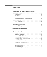
the HP Procurve Switch 2124 Front of the Switch 1-2 Network Ports 1-2 Reset Button 1-2 LEDs 1-3 LED Mode Select Button and Indicator LEDs 1-4 Back of the Switch 1-5 Power Connector 1-5 Features 1-6 Switch Operation Overview 1-6 Address Table Operation 1-6 2 Installing the Switch 2124 - HP J4868A | User Manual - Page 6
3 Troubleshooting Basic Troubleshooting Tips 3-1 Diagnosing with the LEDs 3-3 Hardware Diagnostic Tests 3-5 Testing the Switch by Resetting It 3-5 Testing Twisted-Pair Cabling 3-5 Testing End-to-End Network Communications 3-6 HP Customer Support Services 3-6 A Specifications Physical A-1 - HP J4868A | User Manual - Page 7
networking. HP Procurve Switch 2124 (HP J4868A) Throughout this manual, this switch will be abbreviated as the Switch 2124. The Switch 2124 has 24 auto-sensing 10/100Base-TX RJ-45 ports, and a slot for installing an HP 100-FX SC Transceiver (HP J4853A). You can directly connect end node devices - HP J4868A | User Manual - Page 8
Introducing the HP Procurve Switch 2124 Introducing the HP Procurve Switch 2124 Front of the Switch Front of the Switch Link and Mode LEDs Slot for Power Fault for each HP 100-FX SC Transceiver LED LED port 10/100Base-TX RJ-45 ports Reset button LED Mode Select button and indicator LEDs - HP J4868A | User Manual - Page 9
Introducing the HP Procurve Switch 2124 Introducing the HP Procurve Switch 2124 Front of the Switch LEDs Table 1-1. Switch LEDs Switch LEDs State Meaning Power On (green) Off The switch is receiving power. The switch is NOT receiving power. Fault (orange) Off Blinking* The normal state; - HP J4868A | User Manual - Page 10
HP Procurve Switch 2124 Introducing the HP Procurve Switch 2124 Front of the Switch LED Mode Select Button and Indicator LEDs To optimize the amount of information that can be displayed for each of the switch ports without overwhelming you with LEDs, the Switch 2124 uses a Mode LED for each port - HP J4868A | User Manual - Page 11
Introducing the HP Procurve Switch 2124 Introducing the HP Procurve Switch 2124 Back of the Switch Back of the Switch . cooling vent - make sure this is not obstructed for proper switch operation AC power connector Power Connector The Switch 2124 does not have a power switch; it is powered on when - HP J4868A | User Manual - Page 12
the HP Procurve Switch 2124 Introducing the HP Procurve Switch 2124 Features Features The features of the Switch 2124 include: I 24 auto-sensing 10/100Base-TX RJ-45 ports with "HP Auto-MDIX" I a slot for installing an HP 100-FX SC Transceiver (HP J4853A) I plug-and-play networking - all ports are - HP J4868A | User Manual - Page 13
Introducing the HP Procurve Switch 2124 Introducing the HP Procurve Switch 2124 Switch Operation Overview Forwarding, Filtering, Flooding. When the switch receives a packet, it determines the destination address, and looks for the address in the address table. Based on the port location of that - HP J4868A | User Manual - Page 14
- HP J4868A | User Manual - Page 15
. This chapter shows you how to install your Switch 2124. Included Parts The Switch 2124 has the following components shipped with it: I HP Procurve Switch 2124 Installation Guide (J4868-90001), this manual I Customer Support/Warranty booklet I Accessory kit (5064-2085) • two mounting brackets - HP J4868A | User Manual - Page 16
and having a good location for the switch. Please see page 2-3 for some installation precautions. 2. (Optional) Install the transceiver. The Switch 2124 has a slot for installing an HP 100-FX SC Transceiver (HP J4853A). Depending on where you will locate the Switch 2124, it may be easier to install - HP J4868A | User Manual - Page 17
Installation Precautions: Follow these precautions when installing your HP Switch 2124. I The rack or cabinet should be air flow around the sides and back of the switch is not restricted. I Make sure that if no transceiver is installed in the transceiver slot, the cover plate is installed to cover - HP J4868A | User Manual - Page 18
-pair cables for connecting to any network devices including end nodes, such as computers, or to other switches, hubs, and routers. 2 kilometers for full-duplex connections. (When installed in a Switch 2124, the HP 100-FX SC Transceiver operates only in full-duplex mode.) I Installation Location - HP J4868A | User Manual - Page 19
Installing the Switch 2124 Tr a n s c e i v e r Notes Installing the Switch 2124 Installation Procedures 2. Install An Optional Transceiver Install an optional HP 100-FX SC Transceiver into the transceiver slot as shown in the illustration below, or by following the instructions in the manual that - HP J4868A | User Manual - Page 20
Installing the Switch 2124 Installing the Switch 2124 Installation Procedures 3. Verify the Switch Operates Correctly After you have optionally installed a transceiver, but before mounting the switch in its network location, you should first check that it is working properly by plugging it into a - HP J4868A | User Manual - Page 21
the Switch 2124 Installing the Switch 2124 Installation Procedures switch port LEDs Power and Fault LEDs When the switch is powered on, it performs its diagnostic self test. The self test takes approximately 3 seconds to complete. LED Behavior: During the self test: • All the switch and port LEDs - HP J4868A | User Manual - Page 22
Switch 2124 Installation Procedures 4. Mount the Switch After a transceiver has been installed and you have verified that the switch passes its self test, you are ready to mount the switch in a stable location. The Switch 2124 of the 12-24 screws that are supplied with the switch. Plan which four - HP J4868A | User Manual - Page 23
Installing the Switch 2124 Note Installing the Switch 2124 Installation Procedures Steps 2, 3, and 4 below describe a convenient method of mounting the switch in a rack by placing it on two screws that you first install in the rack. You may, instead, just hold the switch with attached brackets up - HP J4868A | User Manual - Page 24
4. Install the other number 12-24 screw into the upper hole in each bracket. Tighten these screws. install additional screw Installing the Switch 2124 Wall Mounting You can mount the switch on a wall as shown in the illustrations below. Caution The switch should be mounted only to a wall - HP J4868A | User Manual - Page 25
Installing the Switch 2124 Installation Procedures 2. Attach the switch to the wall or wood surface with 5/8-inch number 12 wood screws (not included). For "Bookshelf" Wall Mounting For "Flat" Wall Mounting 5/8-inch wood screw 5/8-inch wood screws Installing the Switch 2124 second 5/8-inch - HP J4868A | User Manual - Page 26
Switch 2124 Installation Procedures Horizontal Surface Mounting Place the switch on a table or other horizontal surface. The switch comes with rubber feet in the accessory kit that can be used to help keep the switch cables and switch power cord to the table leg or other part of the surface - HP J4868A | User Manual - Page 27
the Switch 2124 Installing the Switch 2124 Installation Procedures 6. Connect the Network Cables Connect the network cables, described under "Cabling Infrastructure" (page 2-4), from the network devices or your patch panels to the fixed RJ-45 ports on the switch, or to an HP 100-FX SC Transceiver - HP J4868A | User Manual - Page 28
next two pages show fiber-optic connections between the HP 100-FX SC Transceiver installed in Switch 2124 units and other 100Base-FX devices. Because of the fixed full-duplex operation of the transceiver in the Switch 2124, the device at the other end of any such connection must be configured the - HP J4868A | User Manual - Page 29
can also all communicate with the server that is connected to the switch. Because the Switch 2124 has the "HP Auto-MDIX" feature, the connections between the switch and the hubs, and between the switch and end nodes or servers can be through category 5 "straight-through" or "crossover" twistedpair - HP J4868A | User Manual - Page 30
backbone fiber-optic cable Switch 2124 Switch 8000M Switch 2124 Installing the Switch 2124 Note 2-16 The simpler desktop and segment networks shown in the previous two examples can easily be combined and expanded. For example, you could use an HP Procurve Switch 8000M to interconnect each - HP J4868A | User Manual - Page 31
I HP Customer Support Services (page 3-6) Basic Troubleshooting Tips Most problems are caused by the following situations. Check for these items first when starting your troubleshooting: I Connecting the RJ-45 ports to devices that have a fixed full-duplex configuration. The Switch 2124 RJ-45 ports - HP J4868A | User Manual - Page 32
network performance. For more information on possible network problems and their solutions, refer to the technical note "Troubleshooting LAN Performance and Intermittent Connectivity Problems", which can be found on the HP Procurve web site, http://www.hp.com/go/hpprocurve in the Information Library - HP J4868A | User Manual - Page 33
more information. Try power cycling the switch. If the fault indication reoccurs, the switch may have failed. Call your HP-authorized LAN dealer, or use the electronic support services from HP to get assistance. See the Customer Support/Warranty booklet for more information. Troubleshooting 3-3 - HP J4868A | User Manual - Page 34
assistance. See the Customer Support/Warranty booklet for more information. The Switch 2124 supports installation of only the HP J4853A 100-FX SC Transceiver. If you have installed any other transceiver, the Port 25 Link LED will blink simultaneously with the switch Fault LED. Troubleshooting 3-4 - HP J4868A | User Manual - Page 35
cables attached to the Switch 2124 must be compatible with the appropriate standards. To verify that your cable is compatible with these standards, use a qualified cable test device. HP also offers a wire testing service. Contact your HP-authorized LAN dealer or your local HP sales office for more - HP J4868A | User Manual - Page 36
your switch, Hewlett-Packard offers support 24 hours a day, seven days a week through the use of a number of automated electronic services. See the Customer Support/Warranty booklet that came with your switch for information on how to use these services to get technical support. The HP Procurve web - HP J4868A | User Manual - Page 37
A Specifications Physical Width: Depth: Height: Weight : 44.2 cm (17.4 in) 20.5 cm (8.1 in) 4.4 cm (1.7 in) 2.5 kg (5.5 lbs) Electrical The switch automatically adjusts to any voltage between 100-240 volts and either 50 or 60 Hz. AC voltage: 100-240 volts Maximum current: 1.0 A Frequency - HP J4868A | User Manual - Page 38
Specifications Connectors I The 10/100 Mbps RJ-45 twisted-pair ports are compatible with the IEEE 802.3u 100Base-TX and IEEE 802.3 10Base-T standards. I The 100 Mbps SC fiber-optic port on the optional transceiver is compatible with the IEEE 802.3u 100Base-FX standard. Safety The Switch 2124 - HP J4868A | User Manual - Page 39
2124, including minimum pin-out information and specifications for twisted-pair cables. Incorrectly wired cabling is the most common cause of problems for LAN communications. HP recommends that you work with a qualified LAN cable installer for assistance with your cabling requirements. Switch Ports - HP J4868A | User Manual - Page 40
TX specifications, Switch 2124 twisted-pair port to another switch or hub, which typically have MDI-X ports, the Switch 2124 ports operates as an MDI port and connects correctly. If you connect an end node, such as a server or PC which typically have MDI ports, to the Switch 2124, the switch port - HP J4868A | User Manual - Page 41
Switch Ports and Network Cables Switch Ports and Network Cables Twisted-Pair Cable/Connector Pin pin. I For 10 Mbps connections to the ports, you can use 100-ohm differential Category 3, 4, or 5 unshielded (UTP) or shielded (STP) twisted-pair cable, as supported by the IEEE 802.3 10Base-T standard. - HP J4868A | User Manual - Page 42
HP Auto-MDIX" operation of the 10/100 ports on the switch, for all network connections, to PCs, servers or other end nodes, or to hubs or other switches Pin Assignments Switch End (MDI-X) Signal Pins receive + 1 receive - 2 transmit + 3 transmit - 6 Computer, Transceiver, or Other End Pins - HP J4868A | User Manual - Page 43
10 Mbps or 100 Mbps Network Connection The "HP Auto-MDIX" operation of the 10/100 ports on the switch also allows you to use "crossover" cables for all network connections, to PCs, servers or other end nodes, or to hubs or other switches. Cable Diagram. Connector "A" Connector "B" Crossover Cable - HP J4868A | User Manual - Page 44
- HP J4868A | User Manual - Page 45
manual denotes a hazard that can cause injury or death. A CAUTION in the manual Servicing There are no user-serviceable parts inside these products. Any servicing, adjustment, maintenance, or repair must be performed only by service-trained personnel. These products do not have a power switch - HP J4868A | User Manual - Page 46
Safety and EMC Regulatory Statements Safety and EMC Regulatory Statements Informations concernant la sécurité Informations concernant la sécurité ! WARNING CAUTION Symbole de référence à la documentation. Si le produit est marqué de ce symbole, reportez-vous à la documentation du produit afin d' - HP J4868A | User Manual - Page 47
Safety and EMC Regulatory Statements Safety and EMC Regulatory Statements Hinweise zur Sicherheit Hinweise zur Sicherheit ! WARNING CAUTION Symbol für Dokumentationsverweis. Wenn das Produkt mit diesem Symbol markiert ist, schlagen Sie bitte in der Produktdokumentation nach, um mehr - HP J4868A | User Manual - Page 48
Safety and EMC Regulatory Statements Safety and EMC Regulatory Statements Considerazioni sulla sicurezza Considerazioni sulla sicurezza ! WARNING CAUTION Simbolo di riferimento alla documentazione. Se il prodotto è contrassegnato da questo simbolo, fare riferimento alla documentazione sul - HP J4868A | User Manual - Page 49
ón los componentes de metal de la LAN que estén al descubierto. Este aparato no contiene pieza alguna susceptible de reparación por parte del usuario. Todas las reparaciones, ajustes o servicio de mantenimiento debe realizarlos solamente el técnico. Este producto no tiene interruptor de potencia - HP J4868A | User Manual - Page 50
Safety and EMC Regulatory Statements Safety and EMC Regulatory Statements Safety Information (Japan) Safety Information (Japan) C-6 - HP J4868A | User Manual - Page 51
Safety and EMC Regulatory Statements Safety and EMC Regulatory Statements Safety Information (China) Safety Information (China) C-7 - HP J4868A | User Manual - Page 52
to comply with the limits for a Class A digital device, pursuant to Part 15 of the FCC Rules. These limits are designed to provide reasonable energy and, if not installed and used in accordance with the instruction manual, may cause interference to radio communications. Operation of this equipment - HP J4868A | User Manual - Page 53
Korea Safety and EMC Regulatory Statements EMC Regulatory Statements Taiwan Safety and EMC Regulatory Statements C-9 - HP J4868A | User Manual - Page 54
Safety and EMC Regulatory Statements Safety and EMC Regulatory Statements EMC Regulatory Statements European Community C-10 - HP J4868A | User Manual - Page 55
operation ... 1-6 Auto-MDIX see HP Auto-MDIX B back of switch description ... 1-5 power connector ... 1-5 backbone switch topology with ... 2-16 basic troubleshooting tips ... 3-1 blinking LEDs error indications ... 3-3 buttons LED Mode Select button ... 1-4 Reset button ... 1-2 C cabinet mounting - HP J4868A | User Manual - Page 56
LEDs ... 1-4 network ports ... 1-2 Reset button ... 1-2 slot for transceiver module ... 1-2 H horizontal surface, mounting switch on ... 2-12 HP Auto-MDIX description ... 1-6 effect on cable usage ... 2-4, 2-14-2-15, B-2 I included parts ... 2-1 installation connecting the switch to a power source - HP J4868A | User Manual - Page 57
resetting the switch location of Reset button ... 1-2 troubleshooting procedure ... 3-5 S safety and regulatory statements ... C-1 safety specifications ... A-2 segment switch example topology ... 2-15 selecting the Mode LED display ... 1-4 self test LED behavior during ... 2-7 slot for transceiver - HP J4868A | User Manual - Page 58
of improper topology ... 3-2 examples of ... 2-14 transceiver installation ... 2-5 location of slot on switch ... 1-2 supported type ... 2-5 troubleshooting ... 3-1 basic tips ... 3-1 checking the LEDs ... 3-5 common network problems ... 3-1 diagnostic tests ... 3-5 effects of improper topology - HP J4868A | User Manual - Page 59
- HP J4868A | User Manual - Page 60
. All rights reserved. Reproduction, adaptation, or translation without prior written permission is prohibited except as allowed under the copyright laws. Printed in Taiwan June 2001 Manual Part Number J4868-90001 *J4868-90001*
-
 1
1 -
 2
2 -
 3
3 -
 4
4 -
 5
5 -
 6
6 -
 7
7 -
8
-
9
-
10
-
11
-
12
-
13
-
14
-
15
-
16
-
17
-
18
-
19
-
20
-
21
-
22
-
23
-
24
-
25
-
26
-
27
-
28
-
29
-
30
-
31
-
32
-
33
-
34
-
35
-
36
-
37
-
38
-
39
-
40
-
41
-
42
-
43
-
44
-
45
-
46
-
47
-
48
-
49
-
50
-
51
-
52
-
53
-
54
-
55
-
56
-
57
-
58
-
59
-
60
 |
 |

hp
procurve
switch 2124
installation guide
www.hp.com/go/hpprocurve