HP J4868A User Manual - Page 27
Connect the Network Cables, Using the RJ-45 Connectors (10/100Base-TX ports)
 |
View all HP J4868A manuals
Add to My Manuals
Save this manual to your list of manuals |
Page 27 highlights
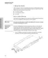
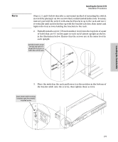
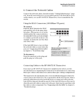
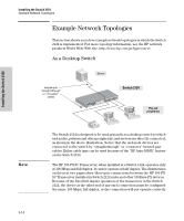
Installing the Switch 2124 Installing the Switch 2124 Installation Procedures 6. Connect the Network Cables Connect the network cables, described under "Cabling Infrastructure" (page 2-4), from the network devices or your patch panels to the fixed RJ-45 ports on the switch, or to an HP 100-FX SC Transceiver, if one is installed in the switch. Using the RJ-45 Connectors (10/100Base-TX ports) To connect: Push the RJ-45 plug into the RJ-45 jack until the tab on the plug clicks into place. When power is on for the switch and for the connected device, the Link LED for the port should light to confirm a powered-on device (for example, an end node) is at the other end of the cable. RJ-45 connector If the Link LED does not go on when the network cable is connected to the port, see "Diagnosing with the LEDs" in chapter 3, "Troubleshooting". To disconnect: Press the small tab on the plug and pull the plug out of the jack. 100-ohm unshielded or shielded twisted-pair cable: • Category 3, 4, or 5 for 10 Mbps ports • Category 5 only for 100 Mbps ports Maximum distance: 100 meters Connecting Cables to the HP 100-FX SC Transceiver If you have an HP 100-FX SC Transceiver installed in the switch, see the documentation accompanying the transceiver for information on connecting fiber-optic cables to the transceiver, and for fiber-optic cabling configurations. The transceiver documentation also covers troubleshooting procedures for connections to the transceiver, but, in general for all the switch ports, when a network cable from an active network device is connected to the port, the Link LED for that port should become lit. If the Link LED does not become lit when the network cable is connected to the port, there may be a problem with the cable or other component. See "Diagnosing with the LEDs" in chapter 3, "Troubleshooting". 2-13
-
 1
1 -
2
-
3
-
4
-
5
-
6
-
7
-
8
-
9
-
10
-
11
-
12
-
13
-
14
-
15
-
16
-
17
-
18
-
19
-
20
-
21
-
 22
22 -
 23
23 -
 24
24 -
 25
25 -
 26
26 -
 27
27 -
 28
28 -
 29
29 -
 30
30 -
 31
31 -
 32
32 -
33
-
34
-
35
-
36
-
37
-
38
-
39
-
40
-
41
-
42
-
43
-
44
-
45
-
46
-
47
-
48
-
49
-
50
-
51
-
52
-
53
-
54
-
55
-
56
-
57
-
58
-
59
-
60
 |
 |
