HP KS159UT HP 550 Notebook PC - Maintenance and Service Guide - Page 76
Two Torx T8M2.0×4.0 screws
 |
UPC - 884420899839
View all HP KS159UT manuals
Add to My Manuals
Save this manual to your list of manuals |
Page 76 highlights
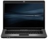
2. Disconnect the fan cable (3) and the Bluetooth module cable (4) from the system board. 3. Remove the following screws: (1) Two Phillips PM2.0×6.0 screws (2) Two Torx T8M2.0×4.0 screws (3) One Torx T8M2.5×4.0 screw 4. Flex the left side of the base enclosure (1) until the external monitor connector (2) is clear of the opening in the base enclosure. 5. Lift the rear edge of the system board (3) until it rests at an angle. 68 Chapter 4 Removal and replacement procedures
-
 1
1 -
2
-
3
-
4
-
5
-
6
-
7
-
8
-
9
-
10
-
11
-
12
-
13
-
14
-
15
-
16
-
17
-
18
-
19
-
20
-
21
-
22
-
23
-
24
-
25
-
26
-
27
-
28
-
29
-
30
-
31
-
32
-
33
-
34
-
35
-
36
-
37
-
38
-
39
-
40
-
41
-
42
-
43
-
44
-
45
-
46
-
47
-
48
-
49
-
50
-
51
-
52
-
53
-
54
-
55
-
56
-
57
-
58
-
59
-
60
-
61
-
62
-
63
-
64
-
65
-
66
-
67
-
68
-
69
-
70
-
 71
71 -
 72
72 -
 73
73 -
 74
74 -
 75
75 -
 76
76 -
 77
77 -
 78
78 -
 79
79 -
 80
80 -
 81
81 -
82
-
83
-
84
-
85
-
86
-
87
-
88
-
89
-
90
-
91
-
92
-
93
-
94
-
95
-
96
-
97
-
98
-
99
-
100
-
101
-
102
-
103
-
104
-
105
-
106
-
107
-
108
-
109
-
110
-
111
-
112
-
113
-
114
-
115
-
116
-
117
-
118
-
119
-
120
-
121
-
122
-
123
-
124
-
125
-
126
-
127
-
128
-
129
-
130
-
131
-
132
-
133
-
134
-
135
-
136
-
137
-
138
-
139
-
140
-
141
-
142
-
143
-
144
-
145
-
146
-
147
-
148
-
149
-
150
 |
 |

2.
Disconnect the fan cable
(3)
and the Bluetooth module cable
(4)
from the system board.
3.
Remove the following screws:
(1)
Two Phillips PM2.0×6.0 screws
(2)
Two Torx T8M2.0×4.0 screws
(3)
One Torx T8M2.5×4.0 screw
4.
Flex the left side of the base enclosure
(1)
until the external monitor connector
(2)
is clear of the
opening in the base enclosure.
5.
Lift the rear edge of the system board
(3)
until it rests at an angle.
68
Chapter 4
Removal and replacement procedures