HP LTE 5000 LTE 5000 Family of Personal Computers Maintenance and Service Guid - Page 145
CPU Cover Assembly, o Standby Suspend button
 |
View all HP LTE 5000 manuals
Add to My Manuals
Save this manual to your list of manuals |
Page 145 highlights
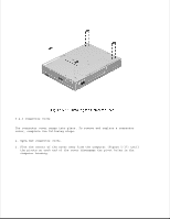
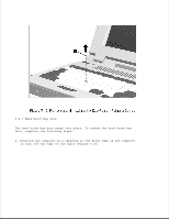
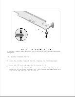
2. Flex the center of the door up until the pivots on each end of the door disengage the pivot holes in the computer housing (Figure 5-21). Reverse this procedure to install the PC Card door. Chapter 5.5 CPU Cover Assembly The CPU cover assembly must be removed to gain access to any of the interior components of the computer, and it is the first component that has to be removed to gain access to the interior components. Maintenance of the CPU cover assembly includes replacement of the following: o CPU cover assembly o Power switch actuator o Standby (Suspend) button o Display switch button Additionally, the integrated microphone can be accessed for service when the CPU cover is removed.
-
 1
1 -
2
-
3
-
4
-
5
-
6
-
7
-
8
-
9
-
10
-
11
-
12
-
13
-
14
-
15
-
16
-
17
-
18
-
19
-
20
-
21
-
22
-
23
-
24
-
25
-
26
-
27
-
28
-
29
-
30
-
31
-
32
-
33
-
34
-
35
-
36
-
37
-
38
-
39
-
40
-
41
-
42
-
43
-
44
-
45
-
46
-
47
-
48
-
49
-
50
-
51
-
52
-
53
-
54
-
55
-
56
-
57
-
58
-
59
-
60
-
61
-
62
-
63
-
64
-
65
-
66
-
67
-
68
-
69
-
70
-
71
-
72
-
73
-
74
-
75
-
76
-
77
-
78
-
79
-
80
-
81
-
82
-
83
-
84
-
85
-
86
-
87
-
88
-
89
-
90
-
91
-
92
-
93
-
94
-
95
-
96
-
97
-
98
-
99
-
100
-
101
-
102
-
103
-
104
-
105
-
106
-
107
-
108
-
109
-
110
-
111
-
112
-
113
-
114
-
115
-
116
-
117
-
118
-
119
-
120
-
121
-
122
-
123
-
124
-
125
-
126
-
127
-
128
-
129
-
130
-
131
-
132
-
133
-
134
-
135
-
136
-
137
-
138
-
139
-
 140
140 -
 141
141 -
 142
142 -
 143
143 -
 144
144 -
 145
145 -
 146
146 -
 147
147 -
 148
148 -
 149
149 -
 150
150 -
151
-
152
-
153
-
154
-
155
-
156
-
157
-
158
-
159
-
160
-
161
-
162
-
163
-
164
-
165
-
166
-
167
-
168
-
169
-
170
-
171
-
172
-
173
-
174
-
175
-
176
-
177
-
178
-
179
-
180
-
181
-
182
-
183
-
184
-
185
-
186
-
187
-
188
-
189
-
190
-
191
-
192
-
193
-
194
-
195
-
196
-
197
-
198
-
199
-
200
-
201
-
202
-
203
-
204
-
205
-
206
-
207
-
208
-
209
-
210
-
211
-
212
-
213
-
214
-
215
-
216
-
217
-
218
-
219
-
220
-
221
-
222
-
223
-
224
-
225
-
226
-
227
-
228
-
229
-
230
-
231
-
232
-
233
-
234
-
235
-
236
-
237
-
238
-
239
-
240
-
241
-
242
-
243
-
244
-
245
-
246
-
247
-
248
-
249
-
250
-
251
-
252
-
253
-
254
-
255
-
256
-
257
-
258
-
259
-
260
-
261
-
262
-
263
-
264
-
265
-
266
-
267
-
268
-
269
-
270
-
271
-
272
-
273
-
274
-
275
-
276
-
277
-
278
-
279
-
280
-
281
-
282
-
283
-
284
-
285
-
286
-
287
-
288
-
289
-
290
-
291
-
292
-
293
-
294
-
295
-
296
-
297
-
298
-
299
-
300
-
301
-
302
-
303
-
304
-
305
-
306
-
307
-
308
-
309
-
310
-
311
-
312
-
313
-
314
 |
 |

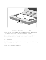
2. Flex the center of the door up until the pivots on each end of the door
disengage the pivot holes in the computer housing (Figure 5-21).
Reverse this procedure to install the PC Card door.
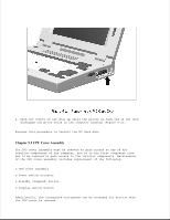
Chapter 5.5 CPU Cover Assembly
The CPU cover assembly must be removed to gain access to any of the
interior components of the computer, and it is the first component that
has to be removed to gain access to the interior components. Maintenance
of the CPU cover assembly includes replacement of the following:
o CPU cover assembly
o Power switch actuator
o Standby (Suspend) button
o Display switch button
Additionally, the integrated microphone can be accessed for service when
the CPU cover is removed.