HP LaserJet 6L Service Manual - Page 110
Separation Pad
 |
View all HP LaserJet 6L manuals
Add to My Manuals
Save this manual to your list of manuals |
Page 110 highlights
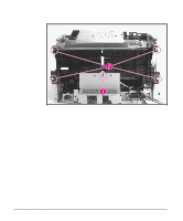
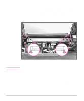
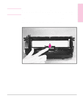
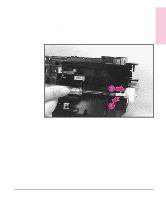
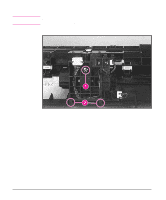
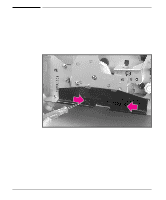
Removal and 6 Replacement Figure 6-33 Separation Pad 1 Remove the Printer Covers, Pickup Roller Assembly (Figures 6-23 and 6-24), and Kick Plate (Figure 6-31). 2 Lift the bottom of the white plastic tab on the rear of the Paper Feed Frame up slightly and slide it up, toward the top of the Paper Feed Frame. This will release the Separation Pad (Figure 6-33). 3 Lift the Separation Pad 90 degrees and slide its mounting pins out of their retainers. Separation Pad Removal Removal and Replacement 6 - 37
-
 1
1 -
2
-
3
-
4
-
5
-
6
-
7
-
8
-
9
-
10
-
11
-
12
-
13
-
14
-
15
-
16
-
17
-
18
-
19
-
20
-
21
-
22
-
23
-
24
-
25
-
26
-
27
-
28
-
29
-
30
-
31
-
32
-
33
-
34
-
35
-
36
-
37
-
38
-
39
-
40
-
41
-
42
-
43
-
44
-
45
-
46
-
47
-
48
-
49
-
50
-
51
-
52
-
53
-
54
-
55
-
56
-
57
-
58
-
59
-
60
-
61
-
62
-
63
-
64
-
65
-
66
-
67
-
68
-
69
-
70
-
71
-
72
-
73
-
74
-
75
-
76
-
77
-
78
-
79
-
80
-
81
-
82
-
83
-
84
-
85
-
86
-
87
-
88
-
89
-
90
-
91
-
92
-
93
-
94
-
95
-
96
-
97
-
98
-
99
-
100
-
101
-
102
-
103
-
104
-
 105
105 -
 106
106 -
 107
107 -
 108
108 -
 109
109 -
 110
110 -
 111
111 -
 112
112 -
 113
113 -
 114
114 -
 115
115 -
116
-
117
-
118
-
119
-
120
-
121
-
122
-
123
-
124
-
125
-
126
-
127
-
128
-
129
-
130
-
131
-
132
-
133
-
134
-
135
-
136
-
137
-
138
-
139
-
140
-
141
-
142
-
143
-
144
-
145
-
146
-
147
-
148
-
149
-
150
-
151
-
152
-
153
-
154
-
155
-
156
-
157
-
158
-
159
-
160
-
161
-
162
-
163
-
164
-
165
-
166
-
167
-
168
-
169
-
170
-
171
-
172
-
173
-
174
-
175
-
176
-
177
-
178
-
179
-
180
-
181
-
182
-
183
-
184
-
185
-
186
-
187
-
188
-
189
-
190
-
191
-
192
-
193
-
194
-
195
-
196
-
197
-
198
-
199
-
200
-
201
-
202
-
203
-
204
 |
 |

Separation Pad
1
Remove the Printer Covers, Pickup Roller Assembly (Figures 6-23 and 6-24), and
Kick Plate (Figure 6-31).
2
Lift the bottom of the white plastic tab on the rear of the Paper Feed Frame up
slightly and slide it up, toward the top of the Paper Feed Frame. This will release the
Separation Pad (Figure 6-33).
3
Lift the Separation Pad 90 degrees and slide its mounting pins out of their retainers.
Separation Pad Removal
Figure 6-33
6
Removal and
Replacement
Removal and Replacement
6 - 37