HP LaserJet 6L Service Manual - Page 70
Basic Sequence of Operation
 |
View all HP LaserJet 6L manuals
Add to My Manuals
Save this manual to your list of manuals |
Page 70 highlights
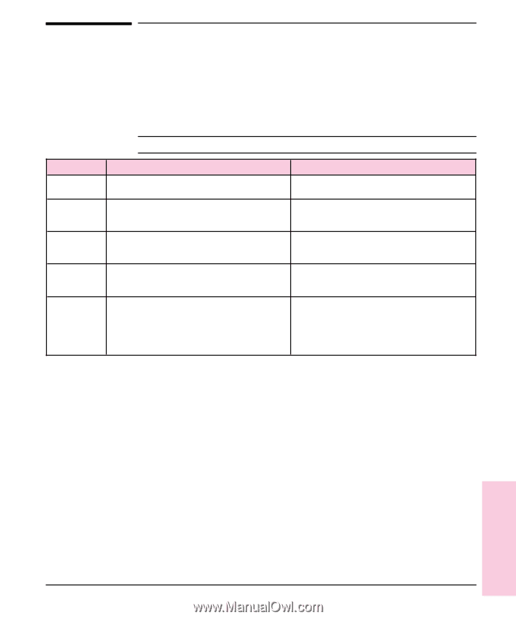
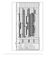
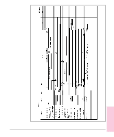
Basic Sequence of Operation The Formatter PCA and the DC Controller PCA share information during printer operation. The DC Controller-to-Formatter Connector (J201) forms a link which operates as a serial data bus. This allows printer status, command information, and dot-image data to be passed between the two PCAs. Figure 5-7 shows the general timing of the printer events. The following events take place during normal printer operation: Table 5-2 Printer Timing Period Timing WAIT From when the paper is inserted to the end of Main Motor initial rotation. STBY (standby) From the end of the WAIT or the LSTR period until the input of the PRNT signal from the Formatter. Or from the end of the LSTR period until power OFF. INTR (initial rotation) From the input of the PRNT signal from the Formatter until the laser diode intensity has been stabilized. PRNT From the end of initial rotation until the Scanner Motor stops. LSTR (last rotation) From the primary voltage (DC) OFF until the Main Motor stops. Purpose Clear the drum surface potential and clean the Transfer Roller. Maintain the printer in ready state. Stabilize the photosensitive drum sensitivity in preparation for printing. Also clean the Transfer Roller. Form images on the photosensitive drum based on the /VDO signal from the Formatter and transfer the image to paper. Deliver the last sheet of paper. Also clean the Transfer Roller. If another PRNT signal is sent from the Formatter, the printer returns to the INTR period. If not, it returns to the STBY period. Refer to Timing Diagram on the next page Functional 5 Overview Functional Overview 5 - 19
-
 1
1 -
2
-
3
-
4
-
5
-
6
-
7
-
8
-
9
-
10
-
11
-
12
-
13
-
14
-
15
-
16
-
17
-
18
-
19
-
20
-
21
-
22
-
23
-
24
-
25
-
26
-
27
-
28
-
29
-
30
-
31
-
32
-
33
-
34
-
35
-
36
-
37
-
38
-
39
-
40
-
41
-
42
-
43
-
44
-
45
-
46
-
47
-
48
-
49
-
50
-
51
-
52
-
53
-
54
-
55
-
56
-
57
-
58
-
59
-
60
-
61
-
62
-
63
-
64
-
 65
65 -
 66
66 -
 67
67 -
 68
68 -
 69
69 -
 70
70 -
 71
71 -
 72
72 -
 73
73 -
 74
74 -
 75
75 -
76
-
77
-
78
-
79
-
80
-
81
-
82
-
83
-
84
-
85
-
86
-
87
-
88
-
89
-
90
-
91
-
92
-
93
-
94
-
95
-
96
-
97
-
98
-
99
-
100
-
101
-
102
-
103
-
104
-
105
-
106
-
107
-
108
-
109
-
110
-
111
-
112
-
113
-
114
-
115
-
116
-
117
-
118
-
119
-
120
-
121
-
122
-
123
-
124
-
125
-
126
-
127
-
128
-
129
-
130
-
131
-
132
-
133
-
134
-
135
-
136
-
137
-
138
-
139
-
140
-
141
-
142
-
143
-
144
-
145
-
146
-
147
-
148
-
149
-
150
-
151
-
152
-
153
-
154
-
155
-
156
-
157
-
158
-
159
-
160
-
161
-
162
-
163
-
164
-
165
-
166
-
167
-
168
-
169
-
170
-
171
-
172
-
173
-
174
-
175
-
176
-
177
-
178
-
179
-
180
-
181
-
182
-
183
-
184
-
185
-
186
-
187
-
188
-
189
-
190
-
191
-
192
-
193
-
194
-
195
-
196
-
197
-
198
-
199
-
200
-
201
-
202
-
203
-
204
 |
 |