HP LaserJet 6p/mp Service Manual - Page 80
Internal assemblies, Control Panel
 |
View all HP LaserJet 6p/mp manuals
Add to My Manuals
Save this manual to your list of manuals |
Page 80 highlights
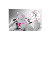
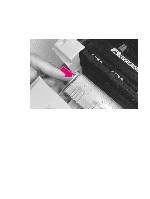
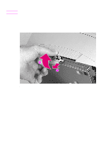
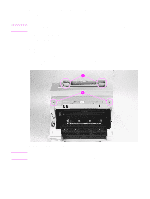
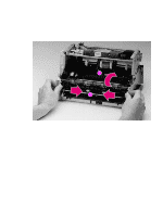
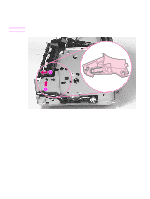
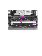
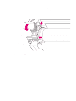
Internal assemblies Note Note Control Panel Procedure for HP LaserJet 5L and 6L 1 Remove the Printer Covers. 2 Use the needlenose pliers to release the Control Panel connector (Figure 6-7,callout 1). 3 Press the tab on the top of the Control Panel downward (Figure 6-7, callout 2). The Control Panel will pop out of the printer chassis. 4 Lift the Control Panel out. Procedure for HP LaserJet 6L Pro 1 Remove the Printer Covers. 2 Press the tab on the top of the Control Panel downward (Figure 6-7, callout 2). The Control Panel will pop out of the printer chassis. The Control Panel on the HP LaserJet 6L Pro is soldered directly to the wiring harness. It is not attached with a connector. Do not try to separate the Control Panel from the wiring harness. 3 Press the tab on the top of the Control Panel downward (Figure 6-7, callout 2).The Control Panel will pop out of the printer chassis. 4 Carefully remove the cable from the guides on the printer chassis. The other end of the wiring harness is attached to the Formatter PCA with a connector. See "Formatter PCA" later in this chapter for more information. 1 2 Figure 6-7 Control Panel removal 78 Removal and replacement EN
-
 1
1 -
2
-
3
-
4
-
5
-
6
-
7
-
8
-
9
-
10
-
11
-
12
-
13
-
14
-
15
-
16
-
17
-
18
-
19
-
20
-
21
-
22
-
23
-
24
-
25
-
26
-
27
-
28
-
29
-
30
-
31
-
32
-
33
-
34
-
35
-
36
-
37
-
38
-
39
-
40
-
41
-
42
-
43
-
44
-
45
-
46
-
47
-
48
-
49
-
50
-
51
-
52
-
53
-
54
-
55
-
56
-
57
-
58
-
59
-
60
-
61
-
62
-
63
-
64
-
65
-
66
-
67
-
68
-
69
-
70
-
71
-
72
-
73
-
74
-
 75
75 -
 76
76 -
 77
77 -
 78
78 -
 79
79 -
 80
80 -
 81
81 -
 82
82 -
 83
83 -
 84
84 -
 85
85 -
86
-
87
-
88
-
89
-
90
-
91
-
92
-
93
-
94
-
95
-
96
-
97
-
98
-
99
-
100
-
101
-
102
-
103
-
104
-
105
-
106
-
107
-
108
-
109
-
110
-
111
-
112
-
113
-
114
-
115
-
116
-
117
-
118
-
119
-
120
-
121
-
122
-
123
-
124
-
125
-
126
-
127
-
128
-
129
-
130
-
131
-
132
-
133
-
134
-
135
-
136
-
137
-
138
-
139
-
140
-
141
-
142
-
143
-
144
-
145
-
146
-
147
-
148
-
149
-
150
-
151
-
152
-
153
-
154
-
155
-
156
-
157
-
158
-
159
-
160
-
161
-
162
-
163
-
164
-
165
-
166
-
167
-
168
-
169
-
170
-
171
-
172
-
173
-
174
-
175
-
176
-
177
-
178
-
179
-
180
-
181
-
182
-
183
-
184
-
185
-
186
-
187
-
188
-
189
-
190
-
191
-
192
-
193
-
194
 |
 |