HP LaserJet 6p/mp Service Manual - Page 81
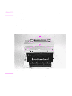
Exit Roller Assembly, Remove Printer Covers.
 |
View all HP LaserJet 6p/mp manuals
Add to My Manuals
Save this manual to your list of manuals |
Page 81 highlights
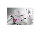
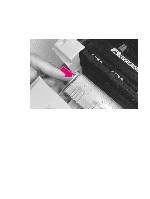
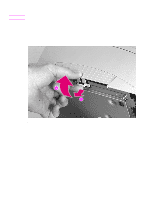
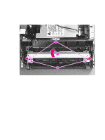
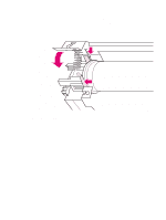
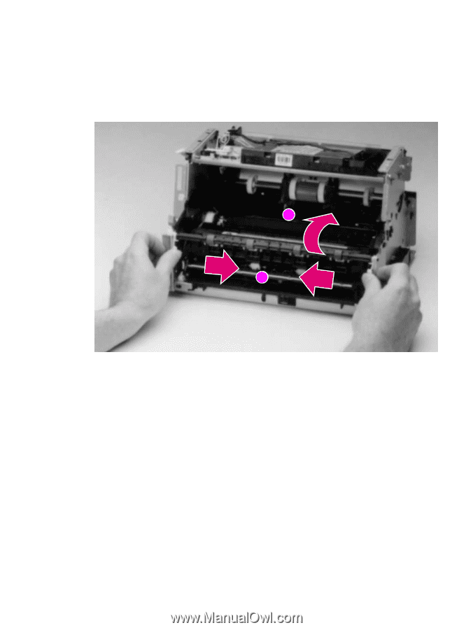
Exit Roller Assembly 1 Remove Printer Covers. 2 Grasp both tabs at the lower ends of the Exit Roller bushings and pull inward. This will release the tabs from the printer chassis (Figure 6-8, callout 1). 3 Rotate the tabs 90 degrees, clear of the printer chassis (Figure 6-8, callout 2). 4 Lift the roller out. 2 1 Figure 6-8 Exit Roller removal To reinstall The end of the Exit Roller that has a gear attached must fit into the gear train. Although it is possible to reinstall the Exit Roller so that the gear end is on the opposite side of the printer, this placement would cause paper path problems. EN Internal assemblies 79
-
 1
1 -
2
-
3
-
4
-
5
-
6
-
7
-
8
-
9
-
10
-
11
-
12
-
13
-
14
-
15
-
16
-
17
-
18
-
19
-
20
-
21
-
22
-
23
-
24
-
25
-
26
-
27
-
28
-
29
-
30
-
31
-
32
-
33
-
34
-
35
-
36
-
37
-
38
-
39
-
40
-
41
-
42
-
43
-
44
-
45
-
46
-
47
-
48
-
49
-
50
-
51
-
52
-
53
-
54
-
55
-
56
-
57
-
58
-
59
-
60
-
61
-
62
-
63
-
64
-
65
-
66
-
67
-
68
-
69
-
70
-
71
-
72
-
73
-
74
-
75
-
 76
76 -
 77
77 -
 78
78 -
 79
79 -
 80
80 -
 81
81 -
 82
82 -
 83
83 -
 84
84 -
 85
85 -
 86
86 -
87
-
88
-
89
-
90
-
91
-
92
-
93
-
94
-
95
-
96
-
97
-
98
-
99
-
100
-
101
-
102
-
103
-
104
-
105
-
106
-
107
-
108
-
109
-
110
-
111
-
112
-
113
-
114
-
115
-
116
-
117
-
118
-
119
-
120
-
121
-
122
-
123
-
124
-
125
-
126
-
127
-
128
-
129
-
130
-
131
-
132
-
133
-
134
-
135
-
136
-
137
-
138
-
139
-
140
-
141
-
142
-
143
-
144
-
145
-
146
-
147
-
148
-
149
-
150
-
151
-
152
-
153
-
154
-
155
-
156
-
157
-
158
-
159
-
160
-
161
-
162
-
163
-
164
-
165
-
166
-
167
-
168
-
169
-
170
-
171
-
172
-
173
-
174
-
175
-
176
-
177
-
178
-
179
-
180
-
181
-
182
-
183
-
184
-
185
-
186
-
187
-
188
-
189
-
190
-
191
-
192
-
193
-
194
 |
 |
EN
Internal assemblies
79
Exit Roller Assembly
1
Remove Printer Covers.
2
Grasp both tabs at the lower ends of the Exit Roller bushings and pull inward. This will release
the tabs from the printer chassis (Figure 6-8, callout 1).
3
Rotate the tabs 90 degrees, clear of the printer chassis (Figure 6-8, callout 2).
4
Lift the roller out.
Figure
6-8
Exit Roller removal
To reinstall
The end of the Exit Roller that has a gear attached must fit into the gear train. Although it is possible
to reinstall the Exit Roller so that the gear end is on the opposite side of the printer, this placement
would cause paper path problems.
1
2