HP Mini 210-1010SS HP Mini 2102, HP Mini 210, and Compaq Mini 210 - Maintenanc - Page 64
Top cover, Remove the six Phillips PM2.0×6.0 screws
 |
View all HP Mini 210-1010SS manuals
Add to My Manuals
Save this manual to your list of manuals |
Page 64 highlights
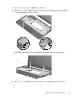
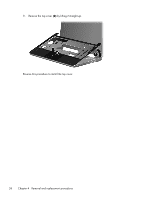
Top cover NOTE: The top cover includes the TouchPad board and bracket. Description In black, for use only with FF computer models In black, for use only with DF computer models In pink In white Spare part number 589676-001 596144-001 608304-001 608305-001 Before removing the top cover, follow these steps: 1. Shut down the computer. If you are unsure whether the computer is off or in Hibernation, turn the computer on, and then shut it down through the operating system. 2. Disconnect all external devices connected to the computer. 3. Disconnect the power from the computer by first unplugging the power cord from the AC outlet and then unplugging the AC adapter from the computer. 4. Remove the battery (see Battery on page 38). 5. Remove the service cover (see Service cover on page 40). 6. Remove the keyboard (see Keyboard on page 52). Remove the top cover. 1. Turn the computer upside down, with the front toward you. 2. Remove the six Phillips PM2.0×6.0 screws (1) and the Phillips PM2.5×4.0 screw (2) that secure the top cover to the base enclosure. 3. Turn the computer right-side up, with the front toward you. 4. Open the computer as far as it will open. 56 Chapter 4 Removal and replacement procedures
-
 1
1 -
2
-
3
-
4
-
5
-
6
-
7
-
8
-
9
-
10
-
11
-
12
-
13
-
14
-
15
-
16
-
17
-
18
-
19
-
20
-
21
-
22
-
23
-
24
-
25
-
26
-
27
-
28
-
29
-
30
-
31
-
32
-
33
-
34
-
35
-
36
-
37
-
38
-
39
-
40
-
41
-
42
-
43
-
44
-
45
-
46
-
47
-
48
-
49
-
50
-
51
-
52
-
53
-
54
-
55
-
56
-
57
-
58
-
 59
59 -
 60
60 -
 61
61 -
 62
62 -
 63
63 -
 64
64 -
 65
65 -
 66
66 -
 67
67 -
 68
68 -
 69
69 -
70
-
71
-
72
-
73
-
74
-
75
-
76
-
77
-
78
-
79
-
80
-
81
-
82
-
83
-
84
-
85
-
86
-
87
-
88
-
89
-
90
-
91
-
92
-
93
-
94
-
95
-
96
-
97
-
98
-
99
-
100
-
101
-
102
-
103
-
104
-
105
-
106
-
107
-
108
-
109
 |
 |
