HP Mini 210-1010SS HP Mini 2102, HP Mini 210, and Compaq Mini 210 - Maintenanc - Page 73
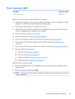
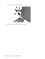
Remove the Phillips PM2.0×4.0 screw, Disconnect the power connector cable
 |
View all HP Mini 210-1010SS manuals
Add to My Manuals
Save this manual to your list of manuals |
Page 73 highlights
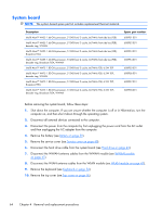
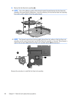
When replacing the system board, be sure that the following components are removed from the defective system board and installed on the replacement system board: ● SIM (see SIM on page 39) ● WWAN module (see WWAN module on page 45) ● WLAN module (see WLAN module on page 47) ● Memory module (see Memory module on page 49) ● RTC battery (see RTC battery on page 51) ● Fan/heat sink assembly (see Fan/heat sink assembly on page 67) Remove the system board: 1. Disconnect the display panel cable (1) from the system board. 2. Disconnect the power connector cable (2) from the system board. 3. Remove the Phillips PM2.0×4.0 screw (1) that secures the system board to the base enclosure. 4. Lift the right side of the system board (2) until it rests at an angle. Component replacement procedures 65
-
 1
1 -
2
-
3
-
4
-
5
-
6
-
7
-
8
-
9
-
10
-
11
-
12
-
13
-
14
-
15
-
16
-
17
-
18
-
19
-
20
-
21
-
22
-
23
-
24
-
25
-
26
-
27
-
28
-
29
-
30
-
31
-
32
-
33
-
34
-
35
-
36
-
37
-
38
-
39
-
40
-
41
-
42
-
43
-
44
-
45
-
46
-
47
-
48
-
49
-
50
-
51
-
52
-
53
-
54
-
55
-
56
-
57
-
58
-
59
-
60
-
61
-
62
-
63
-
64
-
65
-
66
-
67
-
 68
68 -
 69
69 -
 70
70 -
 71
71 -
 72
72 -
 73
73 -
 74
74 -
 75
75 -
 76
76 -
 77
77 -
 78
78 -
79
-
80
-
81
-
82
-
83
-
84
-
85
-
86
-
87
-
88
-
89
-
90
-
91
-
92
-
93
-
94
-
95
-
96
-
97
-
98
-
99
-
100
-
101
-
102
-
103
-
104
-
105
-
106
-
107
-
108
-
109
 |
 |
