HP P6000 HP StorageWorks disk enclosure fan interconnect board replacement ins - Page 4
Verifying proper operation, Returning the failed component, to complete the Power On Self Tests POST.
 |
View all HP P6000 manuals
Add to My Manuals
Save this manual to your list of manuals |
Page 4 highlights
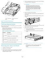
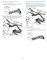
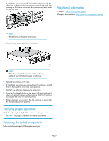
3. If disk drives were only partially removed from the bays, with the drive lever in the open position, reinsert drives fully into each bay, pressing on the lever to secure each drive, remove any labels added to mark the drives. Additional information HP support: http://www.hp.com/support HP support documentation: http://www.hp.com/support/manuals NOTE: Reinstall drives in the same slot locations. 4. Secure the top access panel on the enclosure. NOTE: Place the torx tool back inside the enclosure chassis, on top of the I/O module housing, for future use. 5. Reinstall the enclosure in the rack. 6. If disk drives were previously removed from the enclosure, reinstall them in the bays from which they were removed. 7. Reattach the cabling to the enclosure components. 8. Press the On/Standby button on the power UID bezel and hold it down long enough to power up the enclosure. Wait for the enclosure to complete the Power On Self Tests (POST). 9. Restart all servers with access to the disk enclosure, to ensure that the storage is discovered properly. Verifying proper operation Check the following to verify that the module is working properly: • See Table 1 on page 2 and check for healthy LED patterns. Returning the failed component Follow instructions shipped with the replacement part. Page 4
-
 1
1 -
 2
2 -
 3
3 -
 4
4
 |
 |
