HP Pavilion dv6-3200 HP Pavilion dv6 Entertainment PC - Maintenance and Servic - Page 67
Release the ZIF connector to which the fingerprint reader board cable is attached, and then
 |
View all HP Pavilion dv6-3200 manuals
Add to My Manuals
Save this manual to your list of manuals |
Page 67 highlights
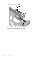
3. Remove the eight Phillips PM2.5×7.0 screws (1) and the three Phillips PM2.5×6.0 screws (2) that secure the top cover to the computer. 4. Release the ZIF connector to which the power button board cable is attached, and then disconnect the power button board cable (1) from the system board. 5. Release the ZIF connector to which the TouchPad cable is attached, and then disconnect the TouchPad cable (2) from the system board. 6. Release the ZIF connector to which the fingerprint reader board cable is attached, and then disconnect the fingerprint reader board cable (3) from the system board. 7. Lift the rear edge of the top cover (1) until it rests at an angle. Component replacement procedures 57
-
 1
1 -
2
-
3
-
4
-
5
-
6
-
7
-
8
-
9
-
10
-
11
-
12
-
13
-
14
-
15
-
16
-
17
-
18
-
19
-
20
-
21
-
22
-
23
-
24
-
25
-
26
-
27
-
28
-
29
-
30
-
31
-
32
-
33
-
34
-
35
-
36
-
37
-
38
-
39
-
40
-
41
-
42
-
43
-
44
-
45
-
46
-
47
-
48
-
49
-
50
-
51
-
52
-
53
-
54
-
55
-
56
-
57
-
58
-
59
-
60
-
61
-
 62
62 -
 63
63 -
 64
64 -
 65
65 -
 66
66 -
 67
67 -
 68
68 -
 69
69 -
 70
70 -
 71
71 -
 72
72 -
73
-
74
-
75
-
76
-
77
-
78
-
79
-
80
-
81
-
82
-
83
-
84
-
85
-
86
-
87
-
88
-
89
-
90
-
91
-
92
-
93
-
94
-
95
-
96
-
97
-
98
-
99
-
100
-
101
-
102
-
103
-
104
-
105
-
106
-
107
-
108
-
109
-
110
-
111
-
112
-
113
-
114
-
115
-
116
-
117
-
118
-
119
-
120
-
121
-
122
-
123
-
124
-
125
-
126
-
127
-
128
-
129
-
130
 |
 |

3.
Remove the eight Phillips PM2.5×7.0 screws
(1)
and the three Phillips PM2.5×6.0 screws
(2)
that
secure the top cover to the computer.
4.
Release the ZIF connector to which the power button board cable is attached, and then disconnect
the power button board cable
(1)
from the system board.
5.
Release the ZIF connector to which the TouchPad cable is attached, and then disconnect the
TouchPad cable
(2)
from the system board.
6.
Release the ZIF connector to which the fingerprint reader board cable is attached, and then
disconnect the fingerprint reader board cable
(3)
from the system board.
7.
Lift the rear edge of the top cover
(1)
until it rests at an angle.
Component replacement procedures
57