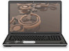
HP Pavilion dv8-1000 HP Pavilion dv8 Entertainment PC - Maintenance and Servic
HP Pavilion dv8-1000 - Entertainment Notebook PC Manual
 |
View all HP Pavilion dv8-1000 manuals
Add to My Manuals
Save this manual to your list of manuals |
HP Pavilion dv8-1000 manual content summary:
- HP Pavilion dv8-1000 | HP Pavilion dv8 Entertainment PC - Maintenance and Servic - Page 1
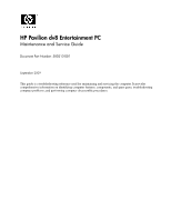
HP Pavilion dv8 Entertainment PC Maintenance and Service Guide Document Part Number: 580213-001 September 2009 This guide is a troubleshooting reference used for maintaining and servicing the computer. It provides comprehensive information on identifying computer features, components, and spare - HP Pavilion dv8-1000 | HP Pavilion dv8 Entertainment PC - Maintenance and Servic - Page 2
to change without notice. The only warranties for HP products and services are set forth in the express warranty statements accompanying such products and services. Nothing herein should be construed as constituting an additional warranty. HP shall not be liable for technical or editorial errors - HP Pavilion dv8-1000 | HP Pavilion dv8 Entertainment PC - Maintenance and Servic - Page 3
to contact the skin or a soft surface, such as pillows or rugs or clothing, during operation. The computer and the AC adapter comply with the user-accessible surface temperature limits defined by the International Standard for Safety of Information Technology Equipment (IEC 60950). - HP Pavilion dv8-1000 | HP Pavilion dv8 Entertainment PC - Maintenance and Servic - Page 4
replacement procedures 4-5 Service tag 4-5 Computer feet 4-6 Battery 4-7 Optical drive 4-8 Mass storage device 4-10 TV tuner module 4-13 RTC battery 4-15 Memory module 4-16 WLAN module 4-17 Switch cover 4-21 Keyboard cover 4-23 Power button board 4-25 Maintenance and Service Guide v - HP Pavilion dv8-1000 | HP Pavilion dv8 Entertainment PC - Maintenance and Servic - Page 5
Contents Bluetooth module 4-26 Keyboard 4-27 Power button board cable 4-30 Bluetooth module cable 4-31 LED board cable 4-32 DMA specifications 6-3 System memory map specifications 6-4 System interrupt specifications 6-4 System I/O address specifications 6-5 vi Maintenance and Service Guide - HP Pavilion dv8-1000 | HP Pavilion dv8 Entertainment PC - Maintenance and Servic - Page 6
requirements Requirements for all countries and regions 10-1 Requirements for specific countries and regions 10-2 11 Recycling Battery 11-1 Display 11-1 Index Index Maintenance and Service Guide vii - HP Pavilion dv8-1000 | HP Pavilion dv8 Entertainment PC - Maintenance and Servic - Page 7
Chipset Graphics Panel Memory Mass storage devices Description HP Pavilion dv8 Entertainment PC Intel® Core™ i7-820QM 1.73-GHz processor (SC turbo up to 3.06 GHz) Intel Core i7-720QM 1.60-GHz processor (SC turbo up to 2.80 GHz) Intel 5 Series express chipsets PM55 - platform controller hub (PCH - HP Pavilion dv8-1000 | HP Pavilion dv8 Entertainment PC - Maintenance and Servic - Page 8
1000 network interface card (NIC) Intel Realtek 8102E 10/100 NIC Ethernet cable included Integrated WLAN options by way of wireless module: 2 wireless antennas built into display assembly Supports no-WLAN option Support antenna with F-PAL or PAL jack (Continued) 1-2 Maintenance and Service Guide - HP Pavilion dv8-1000 | HP Pavilion dv8 Entertainment PC - Maintenance and Servic - Page 9
supporting 1600 × 1200 external resolution at 75 GHz (hot plug/unplug with auto-detect) Supports expansion port 3 Spill-resistant keyboard TouchPad with 2 TouchPad buttons Supports 2-way reader with Digital Persona software support Preinstalled: Windows® 7 End-user replaceable parts: AC adapter - HP Pavilion dv8-1000 | HP Pavilion dv8 Entertainment PC - Maintenance and Servic - Page 10
Security. Then in the System area, click Device Manager. You can also add hardware or modify device configurations using Device Manager. ✎ Windows includes the User Account Control feature to improve the security of your computer. You may be prompted for your permission or password for tasks such as - HP Pavilion dv8-1000 | HP Pavilion dv8 Entertainment PC - Maintenance and Servic - Page 11
the outside of the computer. For optimal transmission, keep the areas immediately around the antennas free from obstructions. (3) Internal digital dual-array microphones (2) Record sound. (4) Webcam light region. These notices are located in Help and Support. 2-2 Maintenance and Service Guide - HP Pavilion dv8-1000 | HP Pavilion dv8 Entertainment PC - Maintenance and Servic - Page 12
turn off the computer. To learn more about your power settings, select Start > Control Panel > System and Security > Power Options. Produce sound. (Continued) Maintenance and Service Guide 2-3 - HP Pavilion dv8-1000 | HP Pavilion dv8 Entertainment PC - Maintenance and Servic - Page 13
) Fingerprint reader Allows a fingerprint logon to Windows, instead of a password logon. *This table describes factory settings. For information about changing factory settings, refer to the user guides located in Help and Support. 2-4 Maintenance and Service Guide - HP Pavilion dv8-1000 | HP Pavilion dv8 Entertainment PC - Maintenance and Servic - Page 14
be used like the keys on an external numeric keypad. Execute frequently used system functions when pressed in combination with the fn key. Maintenance and Service Guide 2-5 - HP Pavilion dv8-1000 | HP Pavilion dv8 Entertainment PC - Maintenance and Servic - Page 15
a Bluetooth device, is on. ■ Amber: All wireless devices are off. On: Num lock is on or the embedded numeric keypad is enabled. (Continued) Maintenance and Service Guide - HP Pavilion dv8-1000 | HP Pavilion dv8 Entertainment PC - Maintenance and Servic - Page 16
12) Drive light ■ Blinking: The hard drive or optical drive is being accessed. ■ Amber: HP ProtectSmart Hard Drive Protection has temporarily parked the internal hard drive. (13) Battery light ■ On: the computer is visible whether the computer is open or closed. Maintenance and Service Guide 2-7 - HP Pavilion dv8-1000 | HP Pavilion dv8 Entertainment PC - Maintenance and Servic - Page 17
view or change pointing device preferences, select Start > Devices and Printers. Then, right-click the device representing your computer, and select Mouse settings. 2-8 Maintenance and Service Guide - HP Pavilion dv8-1000 | HP Pavilion dv8 Entertainment PC - Maintenance and Servic - Page 18
(1) Digital Media Slot (2) Digital Media Slot light (3) Consumer infrared lens Description Supports the following optional digital card formats: ■ Memory Stick (MS) ■ Memory Stick being accessed. Receives a signal from the remote control (select models only). Maintenance and Service Guide 2-9 - HP Pavilion dv8-1000 | HP Pavilion dv8 Entertainment PC - Maintenance and Servic - Page 19
an optional TV antenna or an optional digital cable device that receives standard or high-definition TV broadcasts. Connects an AC adapter. 2-10 Maintenance and Service Guide - HP Pavilion dv8-1000 | HP Pavilion dv8 Entertainment PC - Maintenance and Servic - Page 20
USB device. Connects an optional IEEE 1394 or 1394a device, such as a camcorder. Supports optional ExpressCards. Component Vent Description Enables airflow to cool internal components. ✎ The computer fan internal fan to cycle on and off during routine operation. Maintenance and Service Guide 2-11 - HP Pavilion dv8-1000 | HP Pavilion dv8 Entertainment PC - Maintenance and Servic - Page 21
message, remove the module to restore computer functionality, and then contact technical support through Help and Support. Releases the battery from the battery bay. Enable airflow to cool internal and the 2 memory module slots. Contains the subwoofer speaker. 2-12 Maintenance and Service Guide - HP Pavilion dv8-1000 | HP Pavilion dv8 Entertainment PC - Maintenance and Servic - Page 22
provide the computer serial number and model number provided on the service tag. Item (1) (2) (3) Component Product name Serial number (s/n) a service technician determine what components and parts are needed. This is the alphanumeric identifier used to locate documents, drivers, and support for - HP Pavilion dv8-1000 | HP Pavilion dv8 Entertainment PC - Maintenance and Servic - Page 23
Illustrated parts catalog Computer major components 3-2 Maintenance and Service Guide - HP Pavilion dv8-1000 | HP Pavilion dv8 Entertainment PC - Maintenance and Servic - Page 24
on display assembly spare part numbers. Switch cover 577008-001 Keyboard cover (includes LED board and cable) 577009-001 Keyboard (includes cable): For use in Belgium 578916-A41 For use (not illustrated, includes 7 rubber feet) 496889-001 (Continued) Maintenance and Service Guide 3-3 - HP Pavilion dv8-1000 | HP Pavilion dv8 Entertainment PC - Maintenance and Servic - Page 25
, connector, and 4 isolators) 483862-001 Memory modules (1066-MHz, DDR3): 4096-MB 577606-001 2048-MB 577605-001 1024-MB 577604-001 (Continued) 3-4 Maintenance and Service Guide - HP Pavilion dv8-1000 | HP Pavilion dv8 Entertainment PC - Maintenance and Servic - Page 26
±RW SuperMulti DL Drive 503487-001 Battery: 8-cell, 73-Wh Li-ion battery 480385-001 4-cell, 63-Wh Li-ion battery 516916-001 Maintenance and Service Guide 3-5 - HP Pavilion dv8-1000 | HP Pavilion dv8 Entertainment PC - Maintenance and Servic - Page 27
/microphone module cable Display panel cable Display hinge cover Display Hinge Kit, includes: Display hinge bracket Display left and right hinges Webcam/microphone module Display inverter Spare part number 577003-001 496876-001 577004-001 496874-001 499242-001 498324-001 3-6 Maintenance and - HP Pavilion dv8-1000 | HP Pavilion dv8 Entertainment PC - Maintenance and Servic - Page 28
503487-001 Solid-state drive (includes left and right brackets, Mylar sleeve, connector, and 4 isolators): 256-GB 577609-001 128-GB 577608-001 Maintenance and Service Guide 3-7 - HP Pavilion dv8-1000 | HP Pavilion dv8 Entertainment PC - Maintenance and Servic - Page 29
bezel Mass storage device cover (includes five captive screws, secured by C-clips) WLAN module compartment cover (includes one captive screw, secured by a C-clip) 3-8 Maintenance and Service Guide - HP Pavilion dv8-1000 | HP Pavilion dv8 Entertainment PC - Maintenance and Servic - Page 30
-D61 490371-061 490371-AA1 490371-AR1 490371-AD1 490371-AB1 490371-031 490371-001 465541-001 465540-001 496890-001 371693-001 Maintenance and Service Guide 3-9 - HP Pavilion dv8-1000 | HP Pavilion dv8 Entertainment PC - Maintenance and Servic - Page 31
for use in Argentina Power cord for use in India Display Hinge Kit (includes hinge bracket, and left and right hinges) (Continued) 3-10 Maintenance and Service Guide - HP Pavilion dv8-1000 | HP Pavilion dv8 Entertainment PC - Maintenance and Servic - Page 32
Kit (includes 7 rubber feet) Screw Kit Cable Kit (includes TV tuner module cable) Display inverter Webcam/microphone module 500-GB, 5400-rpm hard drive (includes left and right brackets, Mylar Uruguay, the U.S. Virgin Islands, Venezuela, and Vietnam (Continued) Maintenance and Service Guide 3-11 - HP Pavilion dv8-1000 | HP Pavilion dv8 Entertainment PC - Maintenance and Servic - Page 33
) Keyboard for use in Taiwan (includes keyboard cable) Keyboard for use in South Korea (includes keyboard cable) Keyboard for use in the Netherlands (includes keyboard cable) Keyboard for use in Denmark, Finland, and Norway (includes keyboard cable) (Continued) 3-12 Maintenance and Service Guide - HP Pavilion dv8-1000 | HP Pavilion dv8 Entertainment PC - Maintenance and Servic - Page 34
-001 580987-001 580988-001 580989-001 583053-001 586170-001 Description Keyboard for use in French Canada (includes keyboard cable) Fan/heat sink assembly (includes replacement thermal material) Plastics Kit up to 2.80 GHz, includes replacement thermal material) Maintenance and Service Guide 3-13 - HP Pavilion dv8-1000 | HP Pavilion dv8 Entertainment PC - Maintenance and Servic - Page 35
Phillips P0 and P1 screwdrivers Service considerations The following sections include some in the maintenance instructions. Cables and connectors Ä CAUTION: When servicing the computer, be cables. Be sure that cables are routed in such a way that they cannot be caught or snagged by parts being - HP Pavilion dv8-1000 | HP Pavilion dv8 Entertainment PC - Maintenance and Servic - Page 36
touching pins, leads, and circuitry. Handle electronic components as little as possible. ■ If you remove a component, place it in an electrostatic-safe container. 4-2 Maintenance and Service Guide - HP Pavilion dv8-1000 | HP Pavilion dv8 Entertainment PC - Maintenance and Servic - Page 37
the parts arrive at static-free workstations. ■ Place items equipment. ■ Use conductive field service tools, such as cutters, screwdrivers materials. ■ Keep the work area free of nonconductive materials, such as laminate. Handle these items only at static-free workstations. ■ Avoid contact with pins, - HP Pavilion dv8-1000 | HP Pavilion dv8 Entertainment PC - Maintenance and Servic - Page 38
resistance ■ Static-dissipative tables or floor mats with hard ties to the ground ■ Field Service Kits ■ Static awareness labels ■ Material-handling packages ■ Nonconductive plastic bags, tubes, or mats Floor mats Voltage protection level 1,500 V 7,500 V 5,000 V 4-4 Maintenance and Service Guide - HP Pavilion dv8-1000 | HP Pavilion dv8 Entertainment PC - Maintenance and Servic - Page 39
servicing the computer. Make special note of each screw size and location during removal and replacement. Service provided on the service tag. Item service technician determine what components and parts are needed. This is the alphanumeric identifier used to locate documents, drivers, and support - HP Pavilion dv8-1000 | HP Pavilion dv8 Entertainment PC - Maintenance and Servic - Page 40
. There are 7 rubber feet, in three different sizes (1, 2, and 3), that attach to the base enclosure in the locations shown in the following illustration. 4-6 Maintenance and Service Guide - HP Pavilion dv8-1000 | HP Pavilion dv8 Entertainment PC - Maintenance and Servic - Page 41
, and pivot the front edge of the battery downward until it is seated. The battery release latch automatically locks the battery into place. Maintenance and Service Guide 4-7 - HP Pavilion dv8-1000 | HP Pavilion dv8 Entertainment PC - Maintenance and Servic - Page 42
drive tab access 2, and push the tab forward to release the optical drive from the computer. 4. Remove the optical drive 3 from the computer. 4-8 Maintenance and Service Guide - HP Pavilion dv8-1000 | HP Pavilion dv8 Entertainment PC - Maintenance and Servic - Page 43
the optical drive bracket to the optical drive. c. Remove the optical drive bracket 2. Reverse this procedure to reassemble and install an optical drive. Maintenance and Service Guide 4-9 - HP Pavilion dv8-1000 | HP Pavilion dv8 Entertainment PC - Maintenance and Servic - Page 44
power cord from the AC outlet, and then unplugging the AC adapter from the computer. 4. Remove the battery (see "Battery" on page 4-7). 4-10 Maintenance and Service Guide - HP Pavilion dv8-1000 | HP Pavilion dv8 Entertainment PC - Maintenance and Servic - Page 45
slide the mass storage device 3 away from the mass storage device connector. 5. Remove the mass storage device 4 from the mass storage device bay. Maintenance and Service Guide 4-11 - HP Pavilion dv8-1000 | HP Pavilion dv8 Entertainment PC - Maintenance and Servic - Page 46
device. d. Remove the mass storage device connector 4. e. Remove the four isolators 5. Reverse this procedure to reassemble and install the mass storage devices. 4-12 Maintenance and Service Guide - HP Pavilion dv8-1000 | HP Pavilion dv8 Entertainment PC - Maintenance and Servic - Page 47
the slot at an angle. ✎ The TV tuner module is designed with a notch 4 to prevent incorrect insertion into the TV tuner module slot. Maintenance and Service Guide 4-13 - HP Pavilion dv8-1000 | HP Pavilion dv8 Entertainment PC - Maintenance and Servic - Page 48
Removal and replacement procedures ✎ If the TV tuner module is removed and not replaced, a protective sleeve must be installed on the antenna connector, as shown in the following illustration. Reverse this procedure to install the TV tuner module. 4-14 Maintenance and Service Guide - HP Pavilion dv8-1000 | HP Pavilion dv8 Entertainment PC - Maintenance and Servic - Page 49
device" on page 4-10). Remove the RTC battery: » Lift the RTC battery from the socket. Reverse this procedure to install the RTC battery. Maintenance and Service Guide 4-15 - HP Pavilion dv8-1000 | HP Pavilion dv8 Entertainment PC - Maintenance and Servic - Page 50
. ✎ Memory modules are designed with a notch 3 to prevent incorrect insertion into the memory module slot. Reverse this procedure to install a memory module. 4-16 Maintenance and Service Guide - HP Pavilion dv8-1000 | HP Pavilion dv8 Entertainment PC - Maintenance and Servic - Page 51
the power cord from the AC outlet, and then unplugging the AC adapter from the computer. 4. Remove the battery (see "Battery" on page 4-7). Maintenance and Service Guide 4-17 - HP Pavilion dv8-1000 | HP Pavilion dv8 Entertainment PC - Maintenance and Servic - Page 52
warning message, remove the module to restore computer functionality, and then contact technical support through Help and Support. 1. Loosen the Phillips PM2.5×6.0 captive screw 1 that secures the WLAN module the Plastics Kit, spare part number 580404-001. 4-18 Maintenance and Service Guide - HP Pavilion dv8-1000 | HP Pavilion dv8 Entertainment PC - Maintenance and Servic - Page 53
it away from the slot at an angle. ✎ WLAN modules are designed with a notch 5 to prevent incorrect insertion into the WLAN module slot. Maintenance and Service Guide 4-19 - HP Pavilion dv8-1000 | HP Pavilion dv8 Entertainment PC - Maintenance and Servic - Page 54
sleeve must be installed on the antenna connectors, as shown in the following illustration. Reverse this procedure to install the WLAN module. 4-20 Maintenance and Service Guide - HP Pavilion dv8-1000 | HP Pavilion dv8 Entertainment PC - Maintenance and Servic - Page 55
.5×7.0 screws 1 that secure the switch cover to the computer. 2. Remove the four Phillips PM2.0×4.0 screws 2 that secure the switch cover to the computer. Maintenance and Service Guide 4-21 - HP Pavilion dv8-1000 | HP Pavilion dv8 Entertainment PC - Maintenance and Servic - Page 56
it detaches from the computer. 6. Remove the switch cover 2 by lifting it straight up. Reverse this procedure to install the switch cover. 4-22 Maintenance and Service Guide - HP Pavilion dv8-1000 | HP Pavilion dv8 Entertainment PC - Maintenance and Servic - Page 57
page 4-7). 5. Remove the switch cover (see "Switch cover" on page 4-21). Remove the keyboard cover: 1. Release the keyboard cover 1 by lifting the front edge until it rests at an angle. 2. Lift the keyboard cover 2 as far as the power button board cable allows. Maintenance and Service Guide 4-23 - HP Pavilion dv8-1000 | HP Pavilion dv8 Entertainment PC - Maintenance and Servic - Page 58
Removal and replacement procedures 3. Disconnect the LED board cable 1 from the low insertion force (LIF) connector on the LED board. 4. Remove the keyboard cover 2. Reverse this procedure to install the keyboard cover. 4-24 Maintenance and Service Guide - HP Pavilion dv8-1000 | HP Pavilion dv8 Entertainment PC - Maintenance and Servic - Page 59
page 4-7). 5. Remove the switch cover (see "Switch cover" on page 4-21). 6. Remove the keyboard cover (see "Keyboard cover" on page 4-23). Remove the power button board: 1. Disconnect the power button board cable 1 this procedure to install the power button board. Maintenance and Service Guide 4-25 - HP Pavilion dv8-1000 | HP Pavilion dv8 Entertainment PC - Maintenance and Servic - Page 60
4-7). 5. Remove the following components: a. Switch cover (see "Switch cover" on page 4-21) b. Keyboard cover (see "Keyboard cover" on page 4-23) c. Power button board (see "Power button board" on page 4-25) . Reverse this procedure to install the Bluetooth module. 4-26 Maintenance and Service Guide - HP Pavilion dv8-1000 | HP Pavilion dv8 Entertainment PC - Maintenance and Servic - Page 61
578916-071 578916-111 578916-AB1 578916-141 578916-031 578916-001 Before removing the keyboard, follow these steps: 1. Shut down the computer. If you are unsure whether Switch cover" on page 4-21). 6. Remove the keyboard cover (see "Keyboard cover" on page 4-23). Maintenance and Service Guide 4-27 - HP Pavilion dv8-1000 | HP Pavilion dv8 Entertainment PC - Maintenance and Servic - Page 62
: 1. Turn the computer upside down, with the front toward you. 2. Remove the two Phillips PM2.5×7.0 screws that secure the keyboard to the computer. 3. Turn the computer display-side up, with the front toward you. 4. Open the computer as far as possible. 5. Remove the four Phillips - HP Pavilion dv8-1000 | HP Pavilion dv8 Entertainment PC - Maintenance and Servic - Page 63
cover, and rest it on the display. 8. Release the zero insertion force (ZIF) connector 1 to which the keyboard cable is attached, and disconnect the keyboard cable 2 from the system board. 9. Remove the keyboard. Reverse this procedure to install the keyboard. Maintenance and Service Guide 4-29 - HP Pavilion dv8-1000 | HP Pavilion dv8 Entertainment PC - Maintenance and Servic - Page 64
(see "Keyboard" on page 4-27) Remove the power button board cable: 1. Disconnect the power button board cable 1 from the LIF connector on the system board. 2. Remove the power button board cable 2. Reverse this procedure to install the power button board cable. 4-30 Maintenance and Service Guide - HP Pavilion dv8-1000 | HP Pavilion dv8 Entertainment PC - Maintenance and Servic - Page 65
cover" on page 4-21) b. Keyboard cover (see "Keyboard cover" on page 4-23) c. Power button board (see "Power button board" on page 4-25) d. Keyboard (see "Keyboard" on page 4-27) Remove the cable 3. Reverse this procedure to install the Bluetooth module cable. Maintenance and Service Guide 4-31 - HP Pavilion dv8-1000 | HP Pavilion dv8 Entertainment PC - Maintenance and Servic - Page 66
following components: a. Switch cover (see "Switch cover" on page 4-21) b. Keyboard cover (see "Keyboard cover" on page 4-23) c. Keyboard (see "Keyboard" on page 4-27) Remove the LED board cable: 1. Release the ZIF this procedure to install the LED board cable. 4-32 Maintenance and Service Guide - HP Pavilion dv8-1000 | HP Pavilion dv8 Entertainment PC - Maintenance and Servic - Page 67
a. Switch cover (see "Switch cover" on page 4-21) b. Keyboard cover (see "Keyboard cover" on page 4-23) c. Keyboard (see "Keyboard" on page 4-27) Remove the speaker assembly: 1. Disconnect the speaker 4. Reverse this procedure to install the speaker assembly. Maintenance and Service Guide 4-33 - HP Pavilion dv8-1000 | HP Pavilion dv8 Entertainment PC - Maintenance and Servic - Page 68
components: a. Switch cover (see "Switch cover" on page 4-21) b. Keyboard cover (see "Keyboard cover" on page 4-23) c. Keyboard (see "Keyboard" on page 4-27) d. Speaker assembly (see "Speaker assembly" on page and the routing channel built into the top cover. 4-34 Maintenance and Service Guide - HP Pavilion dv8-1000 | HP Pavilion dv8 Entertainment PC - Maintenance and Servic - Page 69
the display assembly when removing the following screws. Failure to support the display assembly can result in damage to the display assembly and other computer components. 5. covers 1 and the four Phillips PM2.5×7.0 screws 2 on the display bezel lower edge. Maintenance and Service Guide 4-35 - HP Pavilion dv8-1000 | HP Pavilion dv8 Entertainment PC - Maintenance and Servic - Page 70
cables from the tabs. The wireless antenna transceivers and cables are included in the Display Cable Kit, spare part number 496876-001. 4-36 Maintenance and Service Guide - HP Pavilion dv8-1000 | HP Pavilion dv8 Entertainment PC - Maintenance and Servic - Page 71
part number 499242-001. 10. If it is necessary to replace the display hinge cover, display inverter, or webcam/microphone module cable: a. Remove the four Phillips PM2.0×4.0 screws 1 that secure the hinge cover is available using spare part number 577004-001. Maintenance and Service Guide 4-37 - HP Pavilion dv8-1000 | HP Pavilion dv8 Entertainment PC - Maintenance and Servic - Page 72
panel cable to the display panel. b. Disconnect the display panel cable 2 from the display panel. c. Disconnect the display panel cable from the display inverter 3, and remove the display panel cable 4. The display panel cable is included in the Display Cable Kit, spare part number 496876-001. 4-38 - HP Pavilion dv8-1000 | HP Pavilion dv8 Entertainment PC - Maintenance and Servic - Page 73
inverter is available using spare part number 498324-001. 14. If it is necessary to replace the display hinges: a. Remove the two Phillips PM2.0×4.0 screws 1 that secure the display hinge bracket to the display bezel. b. Remove the display hinge bracket 2. Maintenance and Service Guide 4-39 - HP Pavilion dv8-1000 | HP Pavilion dv8 Entertainment PC - Maintenance and Servic - Page 74
are included in the Display Hinge Kit, spare part number 496874-001. Reverse this procedure to reassemble and install the display assembly. 4-40 Maintenance and Service Guide - HP Pavilion dv8-1000 | HP Pavilion dv8 Entertainment PC - Maintenance and Servic - Page 75
4-17) f. Switch cover (see "Switch cover" on page 4-21) g. Keyboard cover (see "Keyboard cover" on page 4-23) h. Keyboard (see "Keyboard" on page 4-27) i. Speaker assembly (see "Speaker assembly" on page module cable (see "Bluetooth module cable" on page 4-31) Maintenance and Service Guide 4-41 - HP Pavilion dv8-1000 | HP Pavilion dv8 Entertainment PC - Maintenance and Servic - Page 76
storage device bay, and the four Phillips PM2.5×4.0 screws 2 in the battery bay, that secure the top cover to the base enclosure. 4-42 Maintenance and Service Guide - HP Pavilion dv8-1000 | HP Pavilion dv8 Entertainment PC - Maintenance and Servic - Page 77
and replacement procedures 6. Release the power connector cable 1 and USB board cable 2 from the clips and routing channel built into the top cover. Maintenance and Service Guide 4-43 - HP Pavilion dv8-1000 | HP Pavilion dv8 Entertainment PC - Maintenance and Servic - Page 78
the top cover until it rests at an angle. 9. Slide the top cover 2 back until the fingerprint reader board cable is accessible. 4-44 Maintenance and Service Guide - HP Pavilion dv8-1000 | HP Pavilion dv8 Entertainment PC - Maintenance and Servic - Page 79
disconnect the fingerprint reader board cable from the system board. 11. Remove the top cover 2. Reverse this procedure to install the top cover. Maintenance and Service Guide 4-45 - HP Pavilion dv8-1000 | HP Pavilion dv8 Entertainment PC - Maintenance and Servic - Page 80
) e. WLAN module (see "WLAN module" on page 4-17) f. Switch cover (see "Switch cover" on page 4-21) g. Keyboard cover (see "Keyboard cover" on page 4-23) h. Keyboard (see "Keyboard" on page 4-27) i. Speaker assembly (see "Speaker assembly" on page 4-33) j. Display assembly (see "Display assembly" on - HP Pavilion dv8-1000 | HP Pavilion dv8 Entertainment PC - Maintenance and Servic - Page 81
board to the top cover. 3. Remove the TouchPad on/off button board 2. Reverse this procedure to install the TouchPad on/off button board. Maintenance and Service Guide 4-47 - HP Pavilion dv8-1000 | HP Pavilion dv8 Entertainment PC - Maintenance and Servic - Page 82
page 4-17) f. Switch cover (see "Switch cover" on page 4-21) g. Keyboard cover (see "Keyboard cover" on page 4-23) h. Keyboard (see "Keyboard" on page 4-27) i. Speaker assembly (see "Speaker assembly" on page 4- 4-60) ■ Processor (see "Processor" on page 4-63) 4-48 Maintenance and Service Guide - HP Pavilion dv8-1000 | HP Pavilion dv8 Entertainment PC - Maintenance and Servic - Page 83
cable from the system board. 6. Disconnect the USB board cable 3 from the system board. 7. Disconnect the power connector cable 4 from the system board. Maintenance and Service Guide 4-49 - HP Pavilion dv8-1000 | HP Pavilion dv8 Entertainment PC - Maintenance and Servic - Page 84
angle. 10. Remove the system board 3 by sliding it up and to the right. Reverse this procedure to install the system board. 4-50 Maintenance and Service Guide - HP Pavilion dv8-1000 | HP Pavilion dv8 Entertainment PC - Maintenance and Servic - Page 85
page 4-23) h. Keyboard (see "Keyboard" on page 4-27) i. Speaker assembly (see "Speaker assembly" on page 4-33) j. Display assembly (see "Display assembly" on page 4-34) k. Top cover (see "Top cover" on page 4-41) l. System board (see "System board" on page 4-48) Maintenance and Service Guide 4-51 - HP Pavilion dv8-1000 | HP Pavilion dv8 Entertainment PC - Maintenance and Servic - Page 86
Removal and replacement procedures Remove the fan: 1. Remove the two Phillips PM2.0×4.0 screws 1 that secure the fan to the base enclosure. 2. Remove the fan 2 from the base enclosure. Reverse this procedure to install the fan. 4-52 Maintenance and Service Guide - HP Pavilion dv8-1000 | HP Pavilion dv8 Entertainment PC - Maintenance and Servic - Page 87
page 4-23) h. Keyboard (see "Keyboard" on page 4-27) i. Speaker assembly (see "Speaker assembly" on page 4-33) j. Display assembly (see "Display assembly" on page 4-34) k. Top cover (see "Top cover" on page 4-41) l. System board (see "System board" on page 4-48) Maintenance and Service Guide 4-53 - HP Pavilion dv8-1000 | HP Pavilion dv8 Entertainment PC - Maintenance and Servic - Page 88
in the correct locations 4 on the subwoofer. These grommets are critical for satisfactory subwoofer performance. Reverse this procedure to install the subwoofer. 4-54 Maintenance and Service Guide - HP Pavilion dv8-1000 | HP Pavilion dv8 Entertainment PC - Maintenance and Servic - Page 89
4-21) g. Keyboard cover (see "Keyboard cover" on page 4-23) h. Keyboard (see "Keyboard" on page 4-27) i. Speaker assembly (see "Speaker assembly" on page 4-33) j. Display assembly (see "Display assembly" on page 4-34) k. Top cover (see "Top cover" on page 4-41) Maintenance and Service Guide 4-55 - HP Pavilion dv8-1000 | HP Pavilion dv8 Entertainment PC - Maintenance and Servic - Page 90
the base enclosure. 3. Remove the audio/infrared board 3 by lifting it straight up. Reverse this procedure to install the audio/infrared board. 4-56 Maintenance and Service Guide - HP Pavilion dv8-1000 | HP Pavilion dv8 Entertainment PC - Maintenance and Servic - Page 91
page 4-17) f. Switch cover (see "Switch cover" on page 4-21) g. Keyboard cover (see "Keyboard cover" on page 4-23) h. Keyboard (see "Keyboard" on page 4-27) i. Speaker assembly (see "Speaker assembly" on page 4-33 Reverse this procedure to install the USB board. Maintenance and Service Guide 4-57 - HP Pavilion dv8-1000 | HP Pavilion dv8 Entertainment PC - Maintenance and Servic - Page 92
page 4-17) f. Switch cover (see "Switch cover" on page 4-21) g. Keyboard cover (see "Keyboard cover" on page 4-23) h. Keyboard (see "Keyboard" on page 4-27) i. Speaker assembly (see "Speaker assembly" on page 4- this procedure to install the power connector cable. 4-58 Maintenance and Service Guide - HP Pavilion dv8-1000 | HP Pavilion dv8 Entertainment PC - Maintenance and Servic - Page 93
page 4-17) f. Switch cover (see "Switch cover" on page 4-21) g. Keyboard cover (see "Keyboard cover" on page 4-23) h. Keyboard (see "Keyboard" on page 4-27) i. Speaker assembly (see "Speaker assembly" on page 4-33 procedure to install the TV tuner module cable. Maintenance and Service Guide 4-59 - HP Pavilion dv8-1000 | HP Pavilion dv8 Entertainment PC - Maintenance and Servic - Page 94
page 4-23) h. Keyboard (see "Keyboard" on page 4-27) i. Speaker assembly (see "Speaker assembly" on page 4-33) j. Display assembly (see "Display assembly" on page 4-34) k. Top cover (see "Top cover" on page 4-41) l. System board (see "System board" on page 4-48) 4-60 Maintenance and Service Guide - HP Pavilion dv8-1000 | HP Pavilion dv8 Entertainment PC - Maintenance and Servic - Page 95
may be necessary to move the fan/heat sink assembly from side to side to detach it. 3. Remove the fan/heat sink assembly 4. Maintenance and Service Guide 4-61 - HP Pavilion dv8-1000 | HP Pavilion dv8 Entertainment PC - Maintenance and Servic - Page 96
the heat sink section 2 that services it. ■ Thermal pads are used on the Northbridge chip 3 and the heat sink section 4 that services it. ■ Thermal pads are components 5 and 7, and heat sink sections 6 and 8 that service them. Replacement thermal material is included with all fan/heat sink assembly - HP Pavilion dv8-1000 | HP Pavilion dv8 Entertainment PC - Maintenance and Servic - Page 97
4-17) f. Switch cover (see "Switch cover" on page 4-21) g. Keyboard cover (see "Keyboard cover" on page 4-23) h. Keyboard (see "Keyboard" on page 4-27) i. Speaker assembly (see "Speaker assembly" on page sink assembly (see "Fan/heat sink assembly" on page 4-60) Maintenance and Service Guide 4-63 - HP Pavilion dv8-1000 | HP Pavilion dv8 Entertainment PC - Maintenance and Servic - Page 98
aligned with the triangle icon 4 embossed on the processor socket when you install the processor. Reverse this procedure to install the processor. 4-64 Maintenance and Service Guide - HP Pavilion dv8-1000 | HP Pavilion dv8 Entertainment PC - Maintenance and Servic - Page 99
exit Setup Utility, use the arrow keys to select Exit > Exit Saving Changes, and then press enter. Your change goes into effect immediately. Maintenance and Service Guide 5-1 - HP Pavilion dv8-1000 | HP Pavilion dv8 Entertainment PC - Maintenance and Servic - Page 100
Utility Navigating and selecting in Setup Utility Because Setup Utility is not Windows based, it does not support the TouchPad. Navigation and selection are by keystroke. ■ To choose a menu or a menu are not changed when you restore the factory default settings. 5-2 Maintenance and Service Guide - HP Pavilion dv8-1000 | HP Pavilion dv8 Entertainment PC - Maintenance and Servic - Page 101
Some of the Setup Utility menu items listed in this chapter may not be supported by your computer. Main menu Select System information Security menu To do this about the processor, memory size, system BIOS, and keyboard controller version (select models only). Select Administrator password Power - HP Pavilion dv8-1000 | HP Pavilion dv8 Entertainment PC - Maintenance and Servic - Page 102
Setup Utility System Configuration menu Select Language Support Button Sound (select models only) Virtualization Technology (select models only) Processor C6 State (select models self-test on a secondary hard drive. Run a diagnostic test on the system memory. 5-4 Maintenance and Service Guide - HP Pavilion dv8-1000 | HP Pavilion dv8 Entertainment PC - Maintenance and Servic - Page 103
to 40,000 ft ✎ Applicable product safety standards specify thermal limits for plastic surfaces. The computer operates well within this range of temperatures. Maintenance and Service Guide 6-1 - HP Pavilion dv8-1000 | HP Pavilion dv8 Entertainment PC - Maintenance and Servic - Page 104
when referring to hard drive storage capacity. Actual accessible capacity is less. Actual drive specifications may differ slightly. ✎ Certain restrictions and exclusions apply. Contact technical support for details. 6-2 Maintenance and Service Guide - HP Pavilion dv8-1000 | HP Pavilion dv8 Entertainment PC - Maintenance and Servic - Page 105
DMA3 Not applicable DMA4 Direct memory access controller DMA5* Not applicable DMA6 Not assigned DMA7 Not assigned *ExpressCard controller can use DMA 1, 2, or 5. Maintenance and Service Guide 6-3 - HP Pavilion dv8-1000 | HP Pavilion dv8 Entertainment PC - Maintenance and Servic - Page 106
101-/102-key or Microsoft natural keyboard IRQ8 System CMOS/real-time clock IRQ12 host controller 2937 Mobile Intel 5 Series express chipset family IRQ17* High-definition possible configurations are IRQ5, IRQ7, IRQ9, IRQ10, or none. ✎ PC Cards may assert IRQ3, IRQ4, IRQ5, IRQ7, IRQ9, IRQ10, - HP Pavilion dv8-1000 | HP Pavilion dv8 Entertainment PC - Maintenance and Servic - Page 107
System timer Standard 101-/102-key or Microsoft natural keyboard Motherboard resources Microsoft ACPI-compliant embedded controller Motherboard resources Standard controller Program interrupt controller Program interrupt controller Maintenance and Service Guide Specifications (Continued) 6-5 - HP Pavilion dv8-1000 | HP Pavilion dv8 Entertainment PC - Maintenance and Servic - Page 108
0200-027F 3B0-3BB 3C0-3DF 400-47F 4D0-4D1 500-57F 1000-1003 1010-101F 2000-20FF 2000-2FFF 3000-4FFF 5000-6FFF 5 Series express chipset family Mobile Intel 5 Series express chipset controller ICH9M-E/M SATA AHCI Controller Mobile Intel 5 Series express chipset family ICH9M-E/M SATA AHCI controller - HP Pavilion dv8-1000 | HP Pavilion dv8 Entertainment PC - Maintenance and Servic - Page 109
: 1 One screw that secures the optical drive to the computer 2 Two screws that secure the switch cover to the computer 3 Two screws that secure the keyboard to the computer Thread 2.5 mm Head diameter 5.0 mm Maintenance and Service Guide 7-1 - HP Pavilion dv8-1000 | HP Pavilion dv8 Entertainment PC - Maintenance and Servic - Page 110
Screw listing Where used: 4 screws that secure the display assembly to the computer Where used: 4 screws that secure the display enclosure to the display assembly 7-2 Maintenance and Service Guide - HP Pavilion dv8-1000 | HP Pavilion dv8 Entertainment PC - Maintenance and Servic - Page 111
Where used: 4 screws that secure the display hinges to the display panel Screw listing Where used: 14 screws that secure the top cover to the base enclosure Maintenance and Service Guide 7-3 - HP Pavilion dv8-1000 | HP Pavilion dv8 Entertainment PC - Maintenance and Servic - Page 112
Screw listing Where used: 5 screws that secure the top cover to the base enclosure Where used: 3 screws that secure the system board to the base enclosure 7-4 Maintenance and Service Guide - HP Pavilion dv8-1000 | HP Pavilion dv8 Entertainment PC - Maintenance and Servic - Page 113
Phillips PM2.0×4.0 screw Screw listing Color Black Quantity 39 Length 4.0 mm Thread 2.0 mm Where used: 2 screws that secure the optical drive bracket to the optical drive Head diameter 4.5 mm Maintenance and Service Guide 7-5 - HP Pavilion dv8-1000 | HP Pavilion dv8 Entertainment PC - Maintenance and Servic - Page 114
Screw listing Where used: 1 Two screws that secure the TV tuner module to the system board 2 Two screws that secure the WLAN module to the system board Where used: 4 screws that secure the switch cover to the computer 7-6 Maintenance and Service Guide - HP Pavilion dv8-1000 | HP Pavilion dv8 Entertainment PC - Maintenance and Servic - Page 115
Where used: One screw that secures the power button board to the top cover Screw listing Where used: 1 Four screws that secure the keyboard to the computer 2 Two screws that secure the speaker assembly to the top cover Maintenance and Service Guide 7-7 - HP Pavilion dv8-1000 | HP Pavilion dv8 Entertainment PC - Maintenance and Servic - Page 116
Screw listing Where used: 2 screws that secure the wireless antenna transceivers to the display enclosure Where used: One screw that secures the webcam/microphone module to the display bezel 7-8 Maintenance and Service Guide - HP Pavilion dv8-1000 | HP Pavilion dv8 Entertainment PC - Maintenance and Servic - Page 117
Where used: 4 screws that secure the display hinge cover to the display bezel Screw listing Where used: 2 screws that secure the display hinge bracket to the display bezel Where used: 4 screws that secure the display hinges to the display panel Maintenance and Service Guide 7-9 - HP Pavilion dv8-1000 | HP Pavilion dv8 Entertainment PC - Maintenance and Servic - Page 118
Screw listing Where used: 3 screws that secure the top cover to the base enclosure Where used: One screw that secures the TouchPad on/off button board to the top cover Where used: 2 screws that secure the fan to the base enclosure 7-10 Maintenance and Service Guide - HP Pavilion dv8-1000 | HP Pavilion dv8 Entertainment PC - Maintenance and Servic - Page 119
Where used: 1 One screw that secures the audio/infrared board to the base enclosure 2 One screw that secures the USB board to the base enclosure Screw listing Where used: One screw that secures the power connector cable and bracket to the base enclosure Maintenance and Service Guide 7-11 - HP Pavilion dv8-1000 | HP Pavilion dv8 Entertainment PC - Maintenance and Servic - Page 120
Screw listing Phillips PM2.5×4.0 screw Color Black Quantity 4 Length 4.0 mm Thread 2.5 mm Where used: 4 screws that secure the top cover to the base enclosure Head diameter 5.0 mm 7-12 Maintenance and Service Guide - HP Pavilion dv8-1000 | HP Pavilion dv8 Entertainment PC - Maintenance and Servic - Page 121
(screws are secured by C clips) 2 One captive screw that secures the WLAN module compartment cover to the computer (screw is secured by a C clip) Maintenance and Service Guide 7-13 - HP Pavilion dv8-1000 | HP Pavilion dv8 Entertainment PC - Maintenance and Servic - Page 122
Screw listing Phillips PM3.0×4.0 screw Color Silver Quantity 4 Length 4.0 mm Thread 3.0 mm Head diameter 5.0 mm Where used: 4 screws that secure the left and right brackets to the mass storage device 7-14 Maintenance and Service Guide - HP Pavilion dv8-1000 | HP Pavilion dv8 Entertainment PC - Maintenance and Servic - Page 123
Phillips PM2.5×5.0 broadhead screw Screw listing Color Silver Quantity 3 Length 5.0 mm Thread 2.5 mm Where used: 3 screws that secure the subwoofer to the base enclosure Head diameter 8.0 mm Maintenance and Service Guide 7-15 - HP Pavilion dv8-1000 | HP Pavilion dv8 Entertainment PC - Maintenance and Servic - Page 124
Screw listing Phillips PM2.0×11.0 captive screw Color Silver Quantity 4 Length 11.0 mm Thread 2.0 mm Head diameter 5.0 mm Where used: 4 captive screws that secure the fan/heat sink assembly to the system board (screws are secured by O rings) 7-16 Maintenance and Service Guide - HP Pavilion dv8-1000 | HP Pavilion dv8 Entertainment PC - Maintenance and Servic - Page 125
Phillips PM2.5×5.0 captive screw Screw listing Color Silver Quantity 2 Length 5.0 mm Thread 2.5 mm Head diameter 5.0 mm Where used: 2 captive screws that secure the fan/heat sink assembly to the system board (screws are secured by O rings) Maintenance and Service Guide 7-17 - HP Pavilion dv8-1000 | HP Pavilion dv8 Entertainment PC - Maintenance and Servic - Page 126
Tools provided by the operating system and HP Recovery Manager software are designed to help you driver without performing a full system recovery. ■ Performing a full system recovery (Recovery Manager software feature). With Recovery Manager, you can recover your full factory image Service Guide 8-1 - HP Pavilion dv8-1000 | HP Pavilion dv8 Entertainment PC - Maintenance and Servic - Page 127
1. Select Start > All Programs > Recovery Manager > Recovery Disc Creation. 2. Follow the on-screen instructions. Backing up your information As you add new software and data files, you should back up your system it into the optical drive of the computer. 8-2 Maintenance and Service Guide - HP Pavilion dv8-1000 | HP Pavilion dv8 Entertainment PC - Maintenance and Servic - Page 128
the speed of the computer. 1. Select Start > All Programs > Maintenance > Backup and Restore. 2. Follow the on-screen instructions to set up and create a backup. ✎ Windows includes the User Account Control feature to improve the security of your computer. You may be prompted for your permission or - HP Pavilion dv8-1000 | HP Pavilion dv8 Entertainment PC - Maintenance and Servic - Page 129
instructions. Performing a recovery ✎ You can recover only files that you have previously backed up. HP recommends that you use HP Start > Help and Support. ✎ Recovery Manager Manager in either of the following ways: ❏ Select Start > All Programs instructions. 8-4 Maintenance and Service Guide - HP Pavilion dv8-1000 | HP Pavilion dv8 Entertainment PC - Maintenance and Servic - Page 130
1394 Pin 1 2 3 4 9 Connector pin assignments Signal TPBTPB+ TPATPA+ Maintenance and Service Guide 9-1 - HP Pavilion dv8-1000 | HP Pavilion dv8 Entertainment PC - Maintenance and Servic - Page 131
Connector pin assignments Audio-in (microphone) Pin 1 2 3 Audio-out (headphone) Signal Audio signal in Audio signal in Ground Pin Signal 1 Audio out, left channel 2 Audio out, right channel 3 Ground 9-2 Maintenance and Service Guide - HP Pavilion dv8-1000 | HP Pavilion dv8 Entertainment PC - Maintenance and Servic - Page 132
9 +5 VDC 10 Ground 11 Monitor detect 12 DDC 2B data 13 Horizontal sync 14 Vertical sync 15 DDC 2B clock Connector pin assignments Maintenance and Service Guide 9-3 - HP Pavilion dv8-1000 | HP Pavilion dv8 Entertainment PC - Maintenance and Servic - Page 133
electronics control 14 Not connected 15 Display data channel (DDC) clock 16 DDC data 17 Ground 18 +5V Power 19 Hot plug detect 9-4 Maintenance and Service Guide - HP Pavilion dv8-1000 | HP Pavilion dv8 Entertainment PC - Maintenance and Servic - Page 134
RJ-45 (network) Pin Signal 1 Transmit + 2 Transmit - 3 Receive + 4 Unused 5 Unused 6 Receive - 7 Unused 8 Unused Connector pin assignments Maintenance and Service Guide 9-5 - HP Pavilion dv8-1000 | HP Pavilion dv8 Entertainment PC - Maintenance and Servic - Page 135
Connector pin assignments Universal Serial Bus Pin Signal 1 +5 VDC 2 Data 3 Data + 4 Ground 9-6 Maintenance and Service Guide - HP Pavilion dv8-1000 | HP Pavilion dv8 Entertainment PC - Maintenance and Servic - Page 136
of an EN 60 320/IEC 320 Standard Sheet C13 connector for mating with the appliance inlet on the back of the computer. Maintenance and Service Guide 10-1 - HP Pavilion dv8-1000 | HP Pavilion dv8 Entertainment PC - Maintenance and Servic - Page 137
plug) must bear the certification mark of the agency responsible for evaluation in the country or region where it will be used. 10-2 Maintenance and Service Guide - HP Pavilion dv8-1000 | HP Pavilion dv8 Entertainment PC - Maintenance and Servic - Page 138
them carefully. ✎ Materials Disposal. This HP product contains mercury in the backlight in .eiae.org. This section provides disassembly instructions for the display assembly. The display procedures provided in this chapter are general disassembly instructions. Specific details, such as screw sizes, - HP Pavilion dv8-1000 | HP Pavilion dv8 Entertainment PC - Maintenance and Servic - Page 139
the top and bottom inside edges 2 of the display bezel until the bezel disengages from the display assembly. 3. Remove the display bezel 3. 11-2 Maintenance and Service Guide - HP Pavilion dv8-1000 | HP Pavilion dv8 Entertainment PC - Maintenance and Servic - Page 140
4. Disconnect all display panel cables 1 from the display inverter and remove the inverter 2. Recycling 5. Remove all screws 1 that secure the display panel assembly to the display enclosure. all screws that secure the display panel frame to the display panel. Maintenance and Service Guide 11-3 - HP Pavilion dv8-1000 | HP Pavilion dv8 Entertainment PC - Maintenance and Servic - Page 141
backlight cover. 14. Turn the display panel right-side up. 15. Remove the backlight cables 1 from the clip 2 in the display panel. 11-4 Maintenance and Service Guide - HP Pavilion dv8-1000 | HP Pavilion dv8 Entertainment PC - Maintenance and Servic - Page 142
and handling the backlight to avoid damaging this component and causing exposure to the mercury. 18. Remove the backlight from the backlight frame. Maintenance and Service Guide 11-5 - HP Pavilion dv8-1000 | HP Pavilion dv8 Entertainment PC - Maintenance and Servic - Page 143
4 that secures the LCD panel to the display rear panel. 23. Remove the LCD panel. 24. Recycle the LCD panel and backlight. 11-6 Maintenance and Service Guide - HP Pavilion dv8-1000 | HP Pavilion dv8 Entertainment PC - Maintenance and Servic - Page 144
31 Blu-ray ROM DVD±RW SuperMulti DL Drive precautions 4-2 removal 4-8 spare part numbers 3-5, 3-7, 3-11, 4-8 specifications 6-3 Maintenance and Service Guide boot options 5-4 boot order 5-4 bottom components 2-12 button components 2-3 button sound 5-4 buttons media 2-4 next/fast forward 2-4 optical - HP Pavilion dv8-1000 | HP Pavilion dv8 Entertainment PC - Maintenance and Servic - Page 145
number 3-6, 3-10, 4-40 display hinges removal 4-39 spare part number 3-6, 3-10, 4-40 display inverter removal 4-39, 11-3 spare part number 3-6, 3-11, 4-39 display panel cable removal 4-38 spare 2-10 audio-out 2-10 headphone 2-10 microphone 2-10 network 2-11 Index-2 Maintenance and Service Guide - HP Pavilion dv8-1000 | HP Pavilion dv8 Entertainment PC - Maintenance and Servic - Page 146
keyboard cover removal 4-23 spare part number 3-3, 3-12, 4-23 keys esc 2-5 fn 2-5 function 2-5 integrated numeric keypad 2-5 Windows applications 2-5 Windows logo 2-5 L LAN Power Saving 5-4 language support play/pause button 2-4 pointing device illustrated 2-8 Maintenance and Service Guide Index-3 - HP Pavilion dv8-1000 | HP Pavilion dv8 Entertainment PC - Maintenance and Servic - Page 147
1-1 display panel 1-1 docking 1-3 Ethernet 1-2 external media card 1-3 graphics 1-1 keyboard 1-3 mass storage device 1-1, 1-2 memory 1-1 microphone 1-2 operating system 1-3 optical Blu-ray ROM DVD±RW SuperMulti DL Drive 6-3 computer 6-1 display assembly 6-2 Maintenance and Service Guide - HP Pavilion dv8-1000 | HP Pavilion dv8 Entertainment PC - Maintenance and Servic - Page 148
tuner module removal 4-13 spare part numbers 3-5, 3-10, 4-13 TV tuner module cable, removal 4-59 TV tuner, product description 1-2 Maintenance and Service Guide Index U Universal Serial Bus (USB) port connector pinout 9-6 location 2-10, 2-11 USB board removal 4-57 spare part number 3-4, 3-13, 4-57
-
 1
1 -
 2
2 -
 3
3 -
 4
4 -
 5
5 -
 6
6 -
 7
7 -
8
-
9
-
10
-
11
-
12
-
13
-
14
-
15
-
16
-
17
-
18
-
19
-
20
-
21
-
22
-
23
-
24
-
25
-
26
-
27
-
28
-
29
-
30
-
31
-
32
-
33
-
34
-
35
-
36
-
37
-
38
-
39
-
40
-
41
-
42
-
43
-
44
-
45
-
46
-
47
-
48
-
49
-
50
-
51
-
52
-
53
-
54
-
55
-
56
-
57
-
58
-
59
-
60
-
61
-
62
-
63
-
64
-
65
-
66
-
67
-
68
-
69
-
70
-
71
-
72
-
73
-
74
-
75
-
76
-
77
-
78
-
79
-
80
-
81
-
82
-
83
-
84
-
85
-
86
-
87
-
88
-
89
-
90
-
91
-
92
-
93
-
94
-
95
-
96
-
97
-
98
-
99
-
100
-
101
-
102
-
103
-
104
-
105
-
106
-
107
-
108
-
109
-
110
-
111
-
112
-
113
-
114
-
115
-
116
-
117
-
118
-
119
-
120
-
121
-
122
-
123
-
124
-
125
-
126
-
127
-
128
-
129
-
130
-
131
-
132
-
133
-
134
-
135
-
136
-
137
-
138
-
139
-
140
-
141
-
142
-
143
-
144
-
145
-
146
-
147
-
148
 |
 |
HP Pavilion dv8 Entertainment PC
Maintenance and Service Guide
Document Part Number: 580213-001
September 2009
This guide is a troubleshooting reference used for maintaining and servicing the computer. It provides
comprehensive information on identifying computer features, components, and spare parts; troubleshooting
computer problems; and performing computer disassembly procedures.