HP Pro 3500 Micro Maintenance & Service Guide Pro 3400 3405 3410 3500 3505 - Page 82
Front I/O and USB Panel Housing Assembly
 |
View all HP Pro 3500 Micro manuals
Add to My Manuals
Save this manual to your list of manuals |
Page 82 highlights
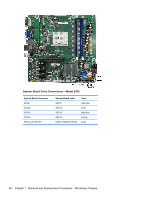
Front I/O and USB Panel Housing Assembly Description Front I/O and USB assembly without card reader Front I/O and USB assembly with card reader Spare part number 667853-001 667852-001 1. Prepare the computer for disassembly (Preparation for Disassembly on page 49). 2. Remove the access panel (Access Panel on page 50) 3. Lay the computer on its side with the front facing toward you. 4. Remove the front bezel (Front Bezel on page 51). 5. Remove the cables from the metal clip built into the bottom of the chassis, and then unplug the three cables that connect the assembly to the system board. The assembly cables connect to the following system board connectors: HP Pro 3400/3410 models F_AUDIO - yellow connector F_USB2 - white connector F_USB3 - white connector HP Pro 3405 models F_AUDIO - yellow connector F_USB1 - white connector F_USB4 - white connector HP Pro 3500 models F_AUDIO - yellow connector F_USB1 - white connector F_USB2 - white connector HP Pro 3505 models F_AUDIO - yellow connector F_USB2 - white connector SPDIF_OUT1 - white connector HP Pro 3515 models F_AUDIO - yellow connector F_USB2 - white connector F_USB30_1 - blue connector 72 Chapter 7 Removal and Replacement Procedures - Microtower Chassis
-
 1
1 -
2
-
3
-
4
-
5
-
6
-
7
-
8
-
9
-
10
-
11
-
12
-
13
-
14
-
15
-
16
-
17
-
18
-
19
-
20
-
21
-
22
-
23
-
24
-
25
-
26
-
27
-
28
-
29
-
30
-
31
-
32
-
33
-
34
-
35
-
36
-
37
-
38
-
39
-
40
-
41
-
42
-
43
-
44
-
45
-
46
-
47
-
48
-
49
-
50
-
51
-
52
-
53
-
54
-
55
-
56
-
57
-
58
-
59
-
60
-
61
-
62
-
63
-
64
-
65
-
66
-
67
-
68
-
69
-
70
-
71
-
72
-
73
-
74
-
75
-
76
-
 77
77 -
 78
78 -
 79
79 -
 80
80 -
 81
81 -
 82
82 -
 83
83 -
 84
84 -
 85
85 -
 86
86 -
 87
87 -
88
-
89
-
90
-
91
-
92
-
93
-
94
-
95
-
96
-
97
-
98
-
99
-
100
-
101
-
102
-
103
-
104
-
105
-
106
-
107
-
108
-
109
-
110
-
111
-
112
-
113
-
114
-
115
-
116
-
117
-
118
-
119
-
120
-
121
-
122
-
123
-
124
-
125
-
126
-
127
-
128
-
129
-
130
-
131
-
132
-
133
-
134
-
135
-
136
-
137
-
138
-
139
-
140
-
141
-
142
-
143
-
144
-
145
-
146
-
147
-
148
-
149
-
150
-
151
-
152
-
153
-
154
-
155
-
156
-
157
-
158
-
159
-
160
-
161
-
162
-
163
-
164
-
165
-
166
-
167
-
168
-
169
-
170
-
171
-
172
-
173
-
174
-
175
-
176
-
177
-
178
-
179
-
180
-
181
-
182
-
183
-
184
-
185
-
186
-
187
-
188
-
189
-
190
-
191
-
192
-
193
-
194
-
195
-
196
-
197
-
198
-
199
-
200
-
201
-
202
-
203
-
204
-
205
-
206
-
207
-
208
-
209
-
210
 |
 |
