HP ProLiant BL660c ISS Technology Focus, Voume 10, Number 1 - Page 2
The Evaluation phase was successful, The Proto One phase is beginning
 |
View all HP ProLiant BL660c manuals
Add to My Manuals
Save this manual to your list of manuals |
Page 2 highlights
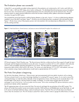
The Evaluation phase was successful In late 2010, we successfully provided cooling capacity for the evaluation unit containing four 42 U racks, each 600 mm (23.62‖) wide x 1200 mm (48‖) deep, plus a center cooling rack. We distributed thermal and pressure sensors throughout the four test racks. The thermal sensors sampled temperatures from the cold (inlet) aisle and hot (exhaust) aisle. We used pressure sensors to capture pressure differences across the hot aisle to identify airflow patterns and ensure acceptable circulation through the MDC system. We simulated the server heat load by installing heating elements in the racks. Figure 1.1A shows multiple heating elements installed in one of the MDC rack bays. Figure 1.1B shows one of 60 thermal sensors we placed in the cold and hot aisles. Figure 1.1B also shows some of the pressure sensors and instrumentation that recorded pressure differentials as air flowed into the cooling rack fans. Figure 1.1. Heat load devices, thermal sensors, and pressure sensors distributed throughout the evaluation unit A B rack bays Heat Loads pressure sensor pressure instrumentation Heat Loads thermal sensor HP thermal engineer Vikash Khanikar says: ―The thermal sensor data lets us determine the air flow capacity through the heat exchanger and the temperature distribution across the racks. Our goal is to achieve 20°C to 25ºC ambient in the cold aisle, which is within acceptable operating parameters for our servers. The heat loads are intended to achieve a server airtemperature delta similar to that found in HP servers. Our servers are rated between 10°C to 35ºC inlet ambient, and most of our customers using a liquid cooled solution would want to operate between 20°C to 25ºC.‖ The Proto One phase is beginning For the Proto One phase, Vikash says, ―We're trying to get more equipment and more realistic situations with our testing. We have noticed a trend in our server technology roadmap for increasing KW use per U space. So we want to ensure this cooling technology can meet the airflow demands of the next-generation servers. One thing we are concerned about is the hot-aisle depth. Some servers, like the ProLiant SL models, are deeper. If we don't leave enough space for the heat exchanger to suck in the hot air, it will re-circulate into the servers. We're also simulating PDUs (power distribution units) to provide more realistic airflow impedance.‖ The HP engineering team will soon receive the Proto One test unit and begin the second phase of the MDC project. This phase will include more realistic server environments using the c7000 enclosure with BladeSystem server heat loads, as well as SL servers to test heat loads from dense, scale-out rack-mount servers. The Proto One unit will also have more thermal sensors than the evaluation unit. We will introduce coolant flow valves and flow meters to gauge the effectiveness of coolant 2
-
 1
1 -
 2
2 -
 3
3 -
 4
4 -
 5
5 -
 6
6 -
 7
7
 |
 |
