HP SignagePlayer mp8000s Hardware Reference Guide
HP SignagePlayer mp8000s Manual
 |
View all HP SignagePlayer mp8000s manuals
Add to My Manuals
Save this manual to your list of manuals |
HP SignagePlayer mp8000s manual content summary:
- HP SignagePlayer mp8000s | Hardware Reference Guide - Page 1
Hardware Reference Guide HP MP 8000s - HP SignagePlayer mp8000s | Hardware Reference Guide - Page 2
HP products and services are set forth in the express warranty statements accompanying such products and services. Nothing herein should be construed as constituting an additional warranty. HP -Packard Company. Hardware Reference Guide HP MP 8000s First Edition (June 2010) Document Part Number: 624909 - HP SignagePlayer mp8000s | Hardware Reference Guide - Page 3
About This Book This guide provides basic information for upgrading this computer model. WARNING! Text set off in this manner indicates that failure to follow directions could result in bodily - HP SignagePlayer mp8000s | Hardware Reference Guide - Page 4
iv About This Book - HP SignagePlayer mp8000s | Hardware Reference Guide - Page 5
Panel Components ...2 Rear Panel Components ...3 Keyboard ...4 Using the Windows Logo Key 5 Serial Number Location ...6 2 Hardware Upgrades ...7 Serviceability Features ...7 Warnings and Cautions ...7 Connecting the Power Cord ...8 Removing the Computer Access Panel 9 Replacing the Computer Access - HP SignagePlayer mp8000s | Hardware Reference Guide - Page 6
Appendix C Security Lock Provisions 32 Installing a Security Lock ...32 HP/Kensington MicroSaver Security Cable Lock 32 Padlock ...33 HP Player PC Security Lock 34 Front Bezel Security 36 Appendix D Electrostatic Discharge 38 Preventing Electrostatic Damage 38 Grounding Methods ...38 Appendix - HP SignagePlayer mp8000s | Hardware Reference Guide - Page 7
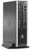
Standard Configuration Features The HP MP 8000s comes with features that may vary depending on the model. For a complete listing of the hardware and software installed in the computer, run the diagnostic utility (included on some computer models only). Figure 1-1 HP MP 8000s Standard Configuration - HP SignagePlayer mp8000s | Hardware Reference Guide - Page 8
icon in the Windows taskbar. NOTE: The Power On Light is normally green when the power is on. If it is flashing red, there is a problem with the computer and it is displaying a diagnostic code. 2 Chapter 1 Product Features - HP SignagePlayer mp8000s | Hardware Reference Guide - Page 9
Rear Panel Components Figure 1-3 Rear Panel Components Table 1-2 Rear Panel Components 1 Line-Out Connector for powered audio 6 Power Cord Connector devices (green) 2 PS/2 Keyboard Connector (purple) 7 TV Tuner (optional) 3 Universal Serial Bus (USB) (6) 8 Line-In Audio Connector (blue - HP SignagePlayer mp8000s | Hardware Reference Guide - Page 10
Keyboard Figure 1-4 Keyboard Components Table 1-3 Keyboard Components 1 Function Keys Perform special functions depending on the software application being used. 2 Editing Keys Include the following: Insert, Home, Page Up, Delete, End, and Page Down. 3 Status Lights Indicate the status of - HP SignagePlayer mp8000s | Hardware Reference Guide - Page 11
Using the Windows Logo Key Use the Windows Logo key in combination with other keys to perform certain functions available in the Windows operating system. Refer to Keyboard on page 4 to identify the Windows Logo key. Table 1-4 Windows Logo Key Functions The following Windows Logo Key functions - HP SignagePlayer mp8000s | Hardware Reference Guide - Page 12
that are located on the top of the computer when it is in the tower configuration. Keep these numbers available for use when contacting customer service for assistance. Figure 1-5 Serial Number and Product ID Location 6 Chapter 1 Product Features - HP SignagePlayer mp8000s | Hardware Reference Guide - Page 13
service. No tools are needed for most of the installation procedures described in this chapter. Warnings and Cautions Before performing upgrades be sure to carefully read all of the applicable instructions, cautions, and warnings in this guide This guide is located on the Web at http://www.hp.com/ - HP SignagePlayer mp8000s | Hardware Reference Guide - Page 14
Connecting the Power Cord When connecting the power supply, it is important to follow the steps below to ensure the power cord does not pull free from the computer. 1. Connect the round end of the power cord to the power supply connector on the rear of the computer (1). 2. Insert the power cord - HP SignagePlayer mp8000s | Hardware Reference Guide - Page 15
Removing the Computer Access Panel To access internal components, you must remove the access panel: 1. Remove/disengage any security devices that prohibit opening the computer. 2. Remove all removable media, such as compact discs or USB flash drives, from the computer. 3. Turn off the computer - HP SignagePlayer mp8000s | Hardware Reference Guide - Page 16
Replacing the Computer Access Panel 1. Align the tabs on the panel with the slots on the chassis then slide the panel towards the front of the chassis until it stops (1). 2. Tighten the thumbscrew to secure the access panel (2). Figure 2-3 Replacing the Computer Access Panel 10 Chapter 2 Hardware - HP SignagePlayer mp8000s | Hardware Reference Guide - Page 17
Removing and Replacing the Front Bezel 1. Remove/disengage any security devices that prohibit opening the computer. 2. Remove all removable media, such as compact discs or USB flash drives, from the computer. 3. Turn off the computer properly through the operating system, then turn off any external - HP SignagePlayer mp8000s | Hardware Reference Guide - Page 18
To replace the front bezel: 1. Insert the three hooks on the bottom side of the bezel into the rectangular holes on the chassis (1) then rotate the top side of the bezel onto the chassis (2) and snap it into place. Figure 2-5 Replacing the Front Bezel 2. Replace the access panel. 3. If the computer - HP SignagePlayer mp8000s | Hardware Reference Guide - Page 19
Removing a Bezel Blank On some models, there is a bezel blank covering the external drive bay that needs to be removed before installing a drive. To remove a bezel blank: 1. Remove the front bezel. 2. Push the two retaining tabs that hold the bezel blank in place towards the outer left edge of the - HP SignagePlayer mp8000s | Hardware Reference Guide - Page 20
removed. To change from the tower configuration to the desktop configuration, reverse the previous steps. NOTE: An optional Quick Release mounting bracket is available from HP for mounting the computer to a wall, desk, or swing arm. 14 Chapter 2 Hardware Upgrades - HP SignagePlayer mp8000s | Hardware Reference Guide - Page 21
be populated with up to two industry-standard SODIMMs. These memory sockets are populated with at least one preinstalled SODIMM. To achieve the maximum memory support, you can populate the system board with up to 8-GB of memory. DDR3-SDRAM SODIMMs For proper system operation, the SODIMMs must be - HP SignagePlayer mp8000s | Hardware Reference Guide - Page 22
Populating SODIMM Sockets There are two SODIMM sockets on the system board, with one socket per channel. The sockets are labeled XMM1 and XMM3. The XMM1 socket operates in memory channel A. The XMM3 socket operates in memory channel B. Figure 2-8 SODIMM Socket Locations Table 2-1 SODIMM Socket - HP SignagePlayer mp8000s | Hardware Reference Guide - Page 23
Installing SODIMMs CAUTION: You must disconnect the power cord and wait approximately 30 seconds for the power to drain before adding or removing memory modules. Regardless of the power-on state, voltage is always supplied to the memory modules as long as the computer is plugged into an active AC - HP SignagePlayer mp8000s | Hardware Reference Guide - Page 24
8. If you are adding a second SODIMM, remove the SODIMM from the top XMM1 socket to access the bottom XMM3 socket. Press outward on the two latches on each side of the SODIMM (1) then pull the SODIMM out of the socket (2). Figure 2-9 Removing a SODIMM 9. Slide the new SODIMM into the socket at - HP SignagePlayer mp8000s | Hardware Reference Guide - Page 25
access panel was removed. The computer automatically recognizes the additional memory when you turn on the computer. Replacing the Optical Drive The HP MP 8000s uses a slimline Serial ATA (SATA) optical drive. Removing the Existing Optical Drive 1. Remove/disengage any security devices that prohibit - HP SignagePlayer mp8000s | Hardware Reference Guide - Page 26
Preparing the New Optical Drive Before the new optical drive can be used, the release latch must be attached. 1. Peel the backing off the adhesive on the release latch. 2. Without allowing the release latch to touch the optical drive, carefully align the holes on the release latch with the pins on - HP SignagePlayer mp8000s | Hardware Reference Guide - Page 27
Installing the New Optical Drive NOTE: If you are installing an optical drive in a bay that did not previously have a drive in it, you must remove the access panel and the bezel blank covering the opening of the bay before proceeding. Follow the procedures in Removing the Computer Access Panel on - HP SignagePlayer mp8000s | Hardware Reference Guide - Page 28
: The HP MP 8000s supports only 2.5-inch Serial ATA (SATA) internal hard drives; parallel ATA (PATA) internal hard drives are not supported. Before you optical drive. Refer to Removing the Existing Optical Drive on page 19 for instructions. 8. Press in the release latch on the left side of the hard - HP SignagePlayer mp8000s | Hardware Reference Guide - Page 29
carrier straight up and out of the chassis. Figure 2-15 Removing the Hard Drive Carrier 10. Remove the four guide screws from the sides of the hard drive carrier. Figure 2-16 Removing the Guide Screws 11. Lift the hard drive up to the top of the carrier (1) and slide the drive out - HP SignagePlayer mp8000s | Hardware Reference Guide - Page 30
. Figure 2-18 Sliding the Hard Drive into the Carrier 13. Set the hard drive down into the bottom of the carrier (1), then replace the four guide screws on the sides of the carrier to secure the drive in the carrier (2). Figure 2-19 Lowering the Hard Drive and Replacing the - HP SignagePlayer mp8000s | Hardware Reference Guide - Page 31
14. To place the hard drive carrier back in the chassis, align the guide screws with the slots on the drive bay, drop the carrier straight down into the drive bay (1), and press the handle on the carrier all - HP SignagePlayer mp8000s | Hardware Reference Guide - Page 32
Installing and Removing a Port Cover An optional rear port cover is available for the computer. To install the port cover: 1. Thread the cables through the bottom hole on the port cover (1) and connect the cables to the rear ports on the computer. 2. Insert the hooks on the port cover into the slots - HP SignagePlayer mp8000s | Hardware Reference Guide - Page 33
25.1 cm 25.4 cm (depth will increase if the computer is equipped with a port security bracket) Approximate Weight 6.75 lb 3.07 kg Weight Supported (maximum distributed load in desktop position) 77 lb 35 kg Temperature Range (values subject to change with increasing altitude above sea level - HP SignagePlayer mp8000s | Hardware Reference Guide - Page 34
Table A-1 Specifications (continued) Power Supply Operating Voltage Range1 Rated Voltage Range1 Rated Line Frequency 90-264 VAC 100-240 VAC 50-60 Hz Power Output 135 W Rated Input Current (maximum)1 2.4A @ 100VAC 1.2A @ 200VAC 1 This system utilizes an active power factor corrected external - HP SignagePlayer mp8000s | Hardware Reference Guide - Page 35
than 60°C (140ºF). Do not disassemble, crush, puncture, short external contacts, or dispose of in fire or water. Replace the battery only with the HP spare designated for this product. CAUTION: Before replacing the battery, it is important to back up the computer CMOS settings. When the battery is - HP SignagePlayer mp8000s | Hardware Reference Guide - Page 36
an internal component to gain access to the battery. 8. Depending on the type of battery holder on the system board, complete the following instructions to replace the battery. Type 1 a. Lift the battery out of its holder. Figure B-1 Removing a Coin Cell Battery (Type 1) b. Slide the replacement - HP SignagePlayer mp8000s | Hardware Reference Guide - Page 37
Type 3 a. Pull back on the clip (1) that is holding the battery in place, and remove the battery (2). b. Insert the new battery and position the clip back into place. Figure B-3 Removing a Coin Cell Battery (Type 3) NOTE: After the battery has been replaced, use the following steps to complete this - HP SignagePlayer mp8000s | Hardware Reference Guide - Page 38
C Security Lock Provisions NOTE: For information on data security features, refer to the Desktop Management Guide and the HP ProtectTools Security Manager Guide (some models) at http://www.hp.com. The security locks displayed below and on the following pages can be used to secure the computer. - HP SignagePlayer mp8000s | Hardware Reference Guide - Page 39
Figure C-2 Installing a Cable with a Port Cover Installed Padlock Figure C-3 Installing a Padlock Installing a Security Lock 33 - HP SignagePlayer mp8000s | Hardware Reference Guide - Page 40
HP Player PC Security Lock 1. Fasten the security cable by looping it around a stationary object. Figure C-4 Securing the Cable to a Fixed Object 2. Thread the keyboard and mouse cables through the lock. Figure C-5 Threading the Keyboard and Mouse Cables 34 Appendix C Security Lock Provisions - HP SignagePlayer mp8000s | Hardware Reference Guide - Page 41
3. Screw the lock to the chassis using the screw provided. Figure C-6 Attaching the Lock to the Chassis 4. Insert the plug end of the security cable into the lock (1) and push the button in (2) to engage the lock. Use the key provided to disengage the lock. Figure C-7 Engaging the Lock Installing a - HP SignagePlayer mp8000s | Hardware Reference Guide - Page 42
Front Bezel Security The front bezel can be locked in place by installing a security screw provided by HP. To install the security screw: 1. Remove/disengage any security devices that prohibit opening the computer. 2. Remove all removable media, such as compact discs or USB - HP SignagePlayer mp8000s | Hardware Reference Guide - Page 43
9. Install the security screw through the middle front bezel release tab and into the chassis to secure the front bezel in place. Figure C-9 Installing the Front Bezel Security Screw 10. Replace the access panel. 11. If the computer was on a stand, replace the stand. 12. Reconnect the power cord and - HP SignagePlayer mp8000s | Hardware Reference Guide - Page 44
work mat. If you do not have any of the suggested equipment for proper grounding, contact an HP authorized dealer, reseller, or service provider. NOTE: For more information on static electricity, contact an HP authorized dealer, reseller, or service provider. 38 Appendix D Electrostatic Discharge - HP SignagePlayer mp8000s | Hardware Reference Guide - Page 45
E Computer Operating Guidelines, Routine Care and Shipping Preparation Computer Operating Guidelines and Routine Care Follow these guidelines to properly set up and care for the computer and monitor: ● Keep the computer away from excessive moisture, direct sunlight, and extremes of heat and cold. ● - HP SignagePlayer mp8000s | Hardware Reference Guide - Page 46
the finish. Safety If any object or liquid falls into the drive, immediately unplug the computer and have it checked by an authorized HP service provider. Shipping Preparation Follow these suggestions when preparing to ship the computer: 1. Back up the hard drive files on PD discs, tape cartridges - HP SignagePlayer mp8000s | Hardware Reference Guide - Page 47
keyboard components 4 connector 3 L LED, system power 2 line-in connector 3 line-out connector 3 locks cable lock 32 front bezel 36 HP Player PC Security Lock 34 padlock 33 M memory module installing 15 specifications 15 microphone connector 2 monitor, connecting 3 mouse connector 3 O optical drive - HP SignagePlayer mp8000s | Hardware Reference Guide - Page 48
13 front bezel 11 hard drive 22 optical drive 19 port cover 26 RJ-45 connector 3 S security cable lock 32 front bezel 36 HP Player PC Security Lock 34 padlock 33 serial number location 6 shipping preparation 40 SODIMMs installing 15 specifications 15 specifications computer 27 SODIMMs 15 status
-
 1
1 -
 2
2 -
 3
3 -
 4
4 -
 5
5 -
 6
6 -
 7
7 -
8
-
9
-
10
-
11
-
12
-
13
-
14
-
15
-
16
-
17
-
18
-
19
-
20
-
21
-
22
-
23
-
24
-
25
-
26
-
27
-
28
-
29
-
30
-
31
-
32
-
33
-
34
-
35
-
36
-
37
-
38
-
39
-
40
-
41
-
42
-
43
-
44
-
45
-
46
-
47
-
48
 |
 |

Hardware Reference Guide
HP MP 8000s