HP StorageWorks 2/16 HP StorageWorks SAN Switch 2/16 V3.1.2 (AA-RR84D-TE, May - Page 23
Installation Guidelines, Selecting an Operating Location, Cooling Requirements
 |
View all HP StorageWorks 2/16 manuals
Add to My Manuals
Save this manual to your list of manuals |
Page 23 highlights
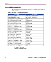
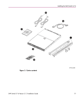
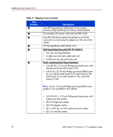
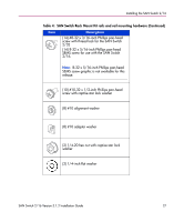
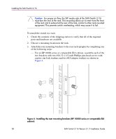
Installing the SAN Switch 2/16 Installation Guidelines Read the following sections for installation guidelines. Install the SAN Switch 2/16 in one of the following ways: ■ As a stand-alone unit on a flat surface. For instructions, see Installing the SAN Switch as a Stand-alone Unit, page 25. ■ In the HP 9000 Series (or comparable) Rack using the SAN Switch Rack Mount Kit supplied with the switch, contents as outlined in Table 3. For instructions, see Installing the Switch in a Rack Using the SAN Switch Rack Mount Kit, page 26. Selecting an Operating Location To ensure correct operation of the switch, the location where the switch is to be used must meet the following requirements: ■ Adequate supply circuit, line fusing, and wire size, as specified by the electrical rating on the switch nameplate. ■ An air flow of at least 300 cubic feet per minute, available in the immediate vicinity of the switch. ■ If installing the switch in the HP 9000 Series, HP System/e or comparable Electronics Industries Association (EIA) rack: - All equipment installed in the rack should have a reliable branch circuit ground connection, and should not rely on a connection to a branch circuit, such as a power strip. - The rack should be balanced and the installed equipment should be within the rack's weight limits. The rack must be mechanically secured to ensure stability in the event of an earthquake. Cooling Requirements Cooling air is drawn into the switch chassis by the fans mounted on the rear of the chassis. The air is expelled through vents in the front of the chassis (the port/cable side). HP cautions that you must install the switch so that air intake and exhaust for all components in the rack flow in the same direction. Caution: Do not block air vents. The switch uses ambient air for cooling. SAN Switch 2/16 Version 3.1.2 Installation Guide 23
-
 1
1 -
2
-
3
-
4
-
5
-
6
-
7
-
8
-
9
-
10
-
11
-
12
-
13
-
14
-
15
-
16
-
17
-
 18
18 -
 19
19 -
 20
20 -
 21
21 -
 22
22 -
 23
23 -
 24
24 -
 25
25 -
 26
26 -
 27
27 -
 28
28 -
29
-
30
-
31
-
32
-
33
-
34
-
35
-
36
-
37
-
38
-
39
-
40
-
41
-
42
-
43
-
44
-
45
-
46
-
47
-
48
-
49
-
50
-
51
-
52
-
53
-
54
-
55
-
56
-
57
-
58
-
59
-
60
-
61
-
62
-
63
-
64
-
65
-
66
-
67
-
68
-
69
-
70
-
71
-
72
-
73
-
74
-
75
-
76
-
77
-
78
-
79
-
80
-
81
-
82
-
83
-
84
-
85
-
86
-
87
-
88
-
89
-
90
-
91
-
92
-
93
-
94
-
95
-
96
-
97
-
98
-
99
-
100
 |
 |