HP StorageWorks 2/16V HP StorageWorks SAN Switch rack mount kit installation i - Page 5
Table 2, shows an inner rail attached to the MP Router
 |
View all HP StorageWorks 2/16V manuals
Add to My Manuals
Save this manual to your list of manuals |
Page 5 highlights
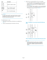
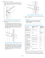
• To attach the inner rails to the SAN Switch 2/32, use the screw holes marked 32. • To attach the inner rails to the 4/8, 4/16, 8/8, or 8/24 SAN Switch, use the five screw holes marked 8. The plenum requires one screw hole marked 8 and one screw hole marked 16, as shown in Figure 8 on page 6. • To attach the inner rails to the 4/32, 4/32B, 4/64, 8/40, or 8/80 SAN Switch, or the 400 MP Router, use the screw holes marked 16, as shown in Figure 7 on page 5. • To attach the inner rails to the MP Router, FCoE Converged Network Switch, or Encryption SAN Switch, use two screw holes marked R and one screw hole marked 16. CAUTION: Be sure to use the screw holes labeled 8 when attaching the inner rails to the SAN Switch 2/16V or SAN Switch 2/16N. 7. Secure the two inner rails (one on each side) to the device using the appropriate number of screws. (See Table 2.) For example, Figure 6 shows an inner rail attached to the MP Router with three screws, using two screw holes marked R and one screw hole marked 16. Attaching both rails requires six screws. Figure 7 shows an inner rail attached to the 4/64 SAN Switch with five screws, using the screw holes marked 16. Attaching both rails requires ten screws. PPOOWRETRS SYSTEM MGMT1 CONSOLE MGMT2 15 14 LINK 13 12 11 SFLICPNE/KGE/bADECT 10 ACTIVITY SPEED 9 8 7 6 5 4 3 2 100-240 VAC 6.0 A 47-63 Hz 1 0 DC OK AC OK 100-240 VAC 6.0 A 47-63 Hz DC OK AC OK Figure 6 Securing the inner rails to the MP Router MR 25007a ! IOIOI SPD LNK MR 2 5018b Figure 7 Securing the inner rails to the 4/64 SAN Switch NOTE: For factory integration only, tighten the #8-32 x 5/16-inch Phillips panhead SEMS screws and torque between 6 and 8 inch-pounds. Page 5
-
 1
1 -
 2
2 -
 3
3 -
 4
4 -
 5
5 -
 6
6
 |
 |
