HP StorageWorks 2/16V HP StorageWorks SAN Switch rack mount kit installation i - Page 6
Installing the plenum (if required), Securing the device HP 9000 Series Rack or HP 10000
 |
View all HP StorageWorks 2/16V manuals
Add to My Manuals
Save this manual to your list of manuals |
Page 6 highlights
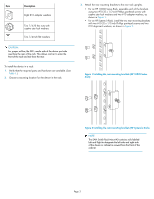
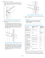
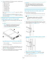
8. If you are installing one of the following switches, install the plenum included in the switch accessory kit: • SAN Switch 2/8V • SAN Switch 2/16 • SAN Switch 2/16V • 4/8 SAN Switch • 4/16 SAN Switch • 4/32B SAN Switch • 8/8 SAN Switch • 8/24 SAN Switch See "Installing the plenum (if required)" on page 6 for installation instructions. If you are not installing one of the devices listed in Step 8, see "Securing the device to the outer rails" on page 6 to complete the rack mount procedure. Installing the plenum (if required) 1. Place the switch (with inner rails attached) on a flat surface. (See Figure 8.) NOTE: Figure 8 illustrates how to attach the plenum to the 4/8 or 4/16 SAN Switch, but this procedure also applies to other switch models that require a plenum. CAUTION: Verify that the open end of the plenum faces the rear of the switch. When installed properly, you should see the plenum's air vent holes on one side, and the front panel of the switch on the other. Securing the device to the outer rails To secure the device to the outer rails: 1. Insert the device with the attached inner rails into the outer rails. NOTE: This step applies to installing a device in an HP 9000 Series Rack, HP 10000 Series Rack, or HP System/e Rack. 2. Insert the device into the rack and install one #10-32 x 1/2-inch Phillips panhead screw with captive star lock washer. Repeat for the other side. (See Figure 9 and Figure 10.) 1 2 IOIOI ! 3 mMAoaTuxTnimtEinugmNtoTscbIrOeew5Nmle:mngothr 1fo3r/6ra4cikn. Figure 9 Securing the device HP 9000 Series Rack or HP 10000 Series Rack 25052a Figure 8 Attaching the plenum to the 4/8 or 4/16 SAN Switch 1. Plenum (installed) 3. Screws that secure the rails 2. 4/8 or 4/16 SAN Switch 2. Locate the four 8-32 x .312 Phillips panhead SEMS screws in the accessory kit. These are the same screws used to attach the inner rails in Step 5 of the preceding section. 3. For each inner rail (left and right), use one screw hole marked 8 and one screw hole marked 16 to attach the plenum. Figure 10 Securing the device (HP System/e Rack) 3. Tighten the hex nuts installed in Step 4 of the section entitled "Installing the SAN Switch Rack Mount Kit in an HP custom rack" on page 2. (See Figure 3.) This completes the rack mount procedure. Page 6
-
 1
1 -
 2
2 -
 3
3 -
 4
4 -
 5
5 -
 6
6
 |
 |
