HP Surestore E Disk Array XP256 Familiarization Guide - Page 29
Operator Panel and CE Panel go on., IND TEST position: The LEDs
 |
View all HP Surestore E Disk Array XP256 manuals
Add to My Manuals
Save this manual to your list of manuals |
Page 29 highlights
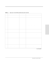
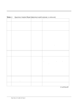
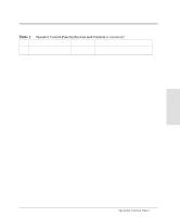
Item Name 15 REMOTE/LOCAL Description Switch 16 IND TEST/CHK RESET Switch 17 BS-ON 18 PS-ON LED (Amber) LED (Green) 19 Disk Control frame Circuit Breaker Breaker 20 Disk Control frame Circuit Breaker Breaker 21 Circuit Breaker (MAIN LINE Breaker switch 1) 22 Circuit Breaker (MAIN LINE Breaker switch 2) Function REMOTE position: Disk array is powered on/off by the instructions from the CPU. LOCAL position: Disk array is powered on/off by the POWER ON/POWER OFF switch. Applies to both storage clusters. IND TEST position: The LEDs on Operator Panel and CE Panel go on. CHK RESET position: The PS ALARM and TH ALARM are reset. Indicates input power is available. Indicates the disk array is powered on. Applies to both storage clusters. Turns off AC input power to storage cluster 1. Turns off AC input power to storage cluster 2. Turns off all AC input power. Turns off all AC input power. Operation 29
-
 1
1 -
2
-
3
-
4
-
5
-
6
-
7
-
8
-
9
-
10
-
11
-
12
-
13
-
14
-
15
-
16
-
17
-
18
-
19
-
20
-
21
-
22
-
23
-
 24
24 -
 25
25 -
 26
26 -
 27
27 -
 28
28 -
 29
29 -
 30
30 -
 31
31 -
 32
32 -
 33
33 -
 34
34 -
35
-
36
-
37
-
38
-
39
-
40
-
41
-
42
-
43
-
44
-
45
-
46
-
47
-
48
-
49
-
50
-
51
-
52
-
53
-
54
-
55
-
56
-
57
-
58
-
59
-
60
-
61
-
62
-
63
-
64
-
65
-
66
-
67
-
68
-
69
-
70
-
71
-
72
 |
 |
