HP Tc4400 Memory Modules - Windows Vista - Page 13
pointing stick cable, is accessible.
 |
UPC - 883585078639
View all HP Tc4400 manuals
Add to My Manuals
Save this manual to your list of manuals |
Page 13 highlights
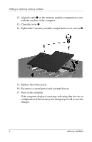
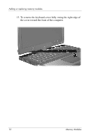
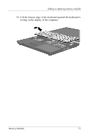
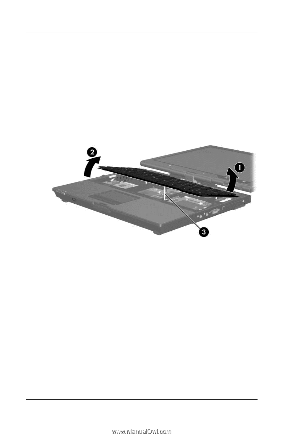
Adding or replacing memory modules 14. Turn the computer display-side up and open it completely. 15. Lift the top edge of the keyboard 1 slightly to detach it from the computer. 16. Lift the bottom edge of the keyboard 2 slightly until the pointing stick cable 3 is accessible. Ä The pointing stick cable is still attached to its zero insertion force (ZIF) connector in the computer. To protect the computer, do not lift the keyboard more than about 2 inches (5.08 cm). Memory Modules 11
-
 1
1 -
2
-
3
-
4
-
5
-
6
-
7
-
 8
8 -
 9
9 -
 10
10 -
 11
11 -
 12
12 -
 13
13 -
 14
14 -
 15
15 -
 16
16 -
 17
17 -
 18
18 -
19
-
20
 |
 |
Adding or replacing memory modules
Memory Modules
11
14. Turn the computer display-side up and open it completely.
15. Lift the top edge of the keyboard
1
slightly to detach it from
the computer.
16. Lift the bottom edge of the keyboard
2
slightly until the
pointing stick cable
3
is accessible.
Ä
The pointing stick cable is still attached to its zero insertion
force (ZIF) connector in the computer. To protect the computer,
do not lift the keyboard more than about 2 inches (5.08 cm).