HP Tc4400 HP Compaq nc4400 Notebook PC - Maintenance and Service Guide - Page 116
Display Assembly, Display Assembly Spare Part Number Information
 |
UPC - 883585078639
View all HP Tc4400 manuals
Add to My Manuals
Save this manual to your list of manuals |
Page 116 highlights
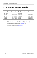
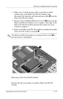
Removal and Replacement Procedures 5.15 Display Assembly Display Assembly Spare Part Number Information 12.1-inch, XGA, TFT display assembly (includes wireless antenna transceivers and cables, microphone, fingerprint reader board, and display cable) 419155-001 1. Prepare the computer for disassembly (Section 5.3). 2. Remove the keyboard cover (Section 5.8). 3. Remove the keyboard (Section 5.9). 4. Close the computer. 5. Turn the computer upside down with the rear panel toward you. 6. Remove the two Torx8 T8M2.0×20.0 screws 1 that secure the base enclosure cover to the computer. 7. Remove the two Torx8 T8M2.0×10.0 screws 2 that secure the display assembly to the computer. Removing the Display Assembly Screws 5-34 Maintenance and Service Guide
-
 1
1 -
2
-
3
-
4
-
5
-
6
-
7
-
8
-
9
-
10
-
11
-
12
-
13
-
14
-
15
-
16
-
17
-
18
-
19
-
20
-
21
-
22
-
23
-
24
-
25
-
26
-
27
-
28
-
29
-
30
-
31
-
32
-
33
-
34
-
35
-
36
-
37
-
38
-
39
-
40
-
41
-
42
-
43
-
44
-
45
-
46
-
47
-
48
-
49
-
50
-
51
-
52
-
53
-
54
-
55
-
56
-
57
-
58
-
59
-
60
-
61
-
62
-
63
-
64
-
65
-
66
-
67
-
68
-
69
-
70
-
71
-
72
-
73
-
74
-
75
-
76
-
77
-
78
-
79
-
80
-
81
-
82
-
83
-
84
-
85
-
86
-
87
-
88
-
89
-
90
-
91
-
92
-
93
-
94
-
95
-
96
-
97
-
98
-
99
-
100
-
101
-
102
-
103
-
104
-
105
-
106
-
107
-
108
-
109
-
110
-
 111
111 -
 112
112 -
 113
113 -
 114
114 -
 115
115 -
 116
116 -
 117
117 -
 118
118 -
 119
119 -
 120
120 -
 121
121 -
122
-
123
-
124
-
125
-
126
-
127
-
128
-
129
-
130
-
131
-
132
-
133
-
134
-
135
-
136
-
137
-
138
-
139
-
140
-
141
-
142
-
143
-
144
-
145
-
146
-
147
-
148
-
149
-
150
-
151
-
152
-
153
-
154
-
155
-
156
-
157
-
158
-
159
-
160
-
161
-
162
-
163
-
164
-
165
-
166
-
167
-
168
-
169
-
170
-
171
-
172
-
173
-
174
-
175
-
176
-
177
-
178
-
179
-
180
-
181
-
182
-
183
-
184
-
185
-
186
-
187
-
188
-
189
-
190
-
191
-
192
-
193
-
194
-
195
-
196
-
197
-
198
-
199
-
200
-
201
-
202
-
203
-
204
-
205
-
206
-
207
-
208
-
209
-
210
-
211
-
212
-
213
-
214
-
215
-
216
-
217
-
218
-
219
-
220
-
221
-
222
-
223
-
224
-
225
-
226
-
227
-
228
 |
 |
