HP Tc4400 HP Compaq nc4400 Notebook PC - Maintenance and Service Guide - Page 129
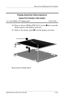
from the display enclosure
 |
UPC - 883585078639
View all HP Tc4400 manuals
Add to My Manuals
Save this manual to your list of manuals |
Page 129 highlights
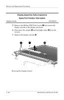
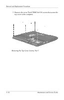
Removal and Replacement Procedures Display Assembly Subcomponents Spare Part Number Information Wireless Antenna Kit 419108-001 32. If it is necessary to replace the wireless antenna transceivers and cables, remove the Phillips PM2.0×6.0 screw 1 that secures each transceiver to the display enclosure. 33. Remove the wireless antenna transceivers 2 and cables 3 from the display enclosure. Removing the Wireless Antenna Transceivers and Cables Reverse the above procedure to reassemble and install the display assembly Maintenance and Service Guide 5-47
-
 1
1 -
2
-
3
-
4
-
5
-
6
-
7
-
8
-
9
-
10
-
11
-
12
-
13
-
14
-
15
-
16
-
17
-
18
-
19
-
20
-
21
-
22
-
23
-
24
-
25
-
26
-
27
-
28
-
29
-
30
-
31
-
32
-
33
-
34
-
35
-
36
-
37
-
38
-
39
-
40
-
41
-
42
-
43
-
44
-
45
-
46
-
47
-
48
-
49
-
50
-
51
-
52
-
53
-
54
-
55
-
56
-
57
-
58
-
59
-
60
-
61
-
62
-
63
-
64
-
65
-
66
-
67
-
68
-
69
-
70
-
71
-
72
-
73
-
74
-
75
-
76
-
77
-
78
-
79
-
80
-
81
-
82
-
83
-
84
-
85
-
86
-
87
-
88
-
89
-
90
-
91
-
92
-
93
-
94
-
95
-
96
-
97
-
98
-
99
-
100
-
101
-
102
-
103
-
104
-
105
-
106
-
107
-
108
-
109
-
110
-
111
-
112
-
113
-
114
-
115
-
116
-
117
-
118
-
119
-
120
-
121
-
122
-
123
-
 124
124 -
 125
125 -
 126
126 -
 127
127 -
 128
128 -
 129
129 -
 130
130 -
 131
131 -
 132
132 -
 133
133 -
 134
134 -
135
-
136
-
137
-
138
-
139
-
140
-
141
-
142
-
143
-
144
-
145
-
146
-
147
-
148
-
149
-
150
-
151
-
152
-
153
-
154
-
155
-
156
-
157
-
158
-
159
-
160
-
161
-
162
-
163
-
164
-
165
-
166
-
167
-
168
-
169
-
170
-
171
-
172
-
173
-
174
-
175
-
176
-
177
-
178
-
179
-
180
-
181
-
182
-
183
-
184
-
185
-
186
-
187
-
188
-
189
-
190
-
191
-
192
-
193
-
194
-
195
-
196
-
197
-
198
-
199
-
200
-
201
-
202
-
203
-
204
-
205
-
206
-
207
-
208
-
209
-
210
-
211
-
212
-
213
-
214
-
215
-
216
-
217
-
218
-
219
-
220
-
221
-
222
-
223
-
224
-
225
-
226
-
227
-
228
 |
 |

Removal and Replacement Procedures
Maintenance and Service Guide
5–47
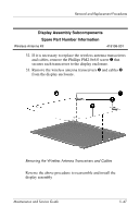
32. If it is necessary to replace the wireless antenna transceivers
and cables, remove the Phillips PM2.0×6.0 screw
1
that
secures each transceiver to the display enclosure.
33. Remove the wireless antenna transceivers
2
and cables
3
from the display enclosure.
Removing the Wireless Antenna Transceivers and Cables
Reverse the above procedure to reassemble and install the
display assembly
Display Assembly Subcomponents
Spare Part Number Information
Wireless Antenna Kit
419108-001