HP Tx2-1370us HP TouchSmart tx2 Notebook PC - Maintenance and Service Guide
HP Tx2-1370us - TouchSmart - Turion X2 Ultra 2.3 GHz Manual
 |
UPC - 884962549247
View all HP Tx2-1370us manuals
Add to My Manuals
Save this manual to your list of manuals |
HP Tx2-1370us manual content summary:
- HP Tx2-1370us | HP TouchSmart tx2 Notebook PC - Maintenance and Service Guide - Page 1
HP TouchSmart tx2 Notebook PC Maintenance and Service Guide - HP Tx2-1370us | HP TouchSmart tx2 Notebook PC - Maintenance and Service Guide - Page 2
or omissions contained herein. This guide is a troubleshooting reference used for maintaining and servicing the computer. It provides comprehensive information on identifying computer features, components, and spare parts; on troubleshooting computer problems; and on performing computer disassembly - HP Tx2-1370us | HP TouchSmart tx2 Notebook PC - Maintenance and Service Guide - Page 3
Safety warning notice WARNING! To reduce the possibility of heat-related injuries or of overheating the computer, do not place the computer directly on your lap or obstruct the computer air vents. Use the computer only on a hard, flat surface. Do not allow another hard surface, such as an adjoining - HP Tx2-1370us | HP TouchSmart tx2 Notebook PC - Maintenance and Service Guide - Page 4
iv Safety warning notice - HP Tx2-1370us | HP TouchSmart tx2 Notebook PC - Maintenance and Service Guide - Page 5
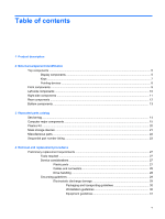
...5 Keys ...7 Pointing devices ...8 Front components ...9 Left-side components ...10 Right-side components ...11 Rear components ...12 Bottom components ...13 3 Illustrated parts catalog Service tag ...14 Computer major components ...15 Plastics Kit ...20 Mass storage devices ...21 Miscellaneous - HP Tx2-1370us | HP TouchSmart tx2 Notebook PC - Maintenance and Service Guide - Page 6
32 Component replacement procedures 33 Service tag ...33 Computer feet ...34 Battery ...35 Pen ...36 Hard drive ...37 RTC battery ...39 Optical drive ... ...72 6 Specifications Computer specifications ...73 12.1-inch, WXGA BrightView display specifications 74 Hard drive specifications ...75 DVD± - HP Tx2-1370us | HP TouchSmart tx2 Notebook PC - Maintenance and Service Guide - Page 7
System interrupt specifications ...78 System I/O address specifications ...79 System memory map specifications 81 7 Screw listing Phillips PM3 Restore to a previous date and time 95 Performing a recovery ...96 Recovering from the recovery discs 96 Recovering from the partition on the hard drive - HP Tx2-1370us | HP TouchSmart tx2 Notebook PC - Maintenance and Service Guide - Page 8
11 Recycling Battery ...103 Display ...104 Index ...109 viii - HP Tx2-1370us | HP TouchSmart tx2 Notebook PC - Maintenance and Service Guide - Page 9
Name Processors Chipset Graphics Panels Memory Description HP TouchSmart tx2 Notebook PC AMD Turion™ 64 Mobile Technology Ultra Dual (multitouch enabled) and EMR support Typical brightness: 200 nits ● Two SODIMM slots ● Customer accessible/upgradable ● Dual-channel support ● DDR2, PC2-6400, 800 - HP Tx2-1370us | HP TouchSmart tx2 Notebook PC - Maintenance and Service Guide - Page 10
MB × 1, 1024 MB × 2, dual-channel) 1024-MB total system memory (1024 MB × 1) ● Supports all 9.5-mm, 6.35-cm (2.5-inch) hard drives ● Serial ATA 500-GB, 5400-rpm 400-GB, 5400 speakers ● Motorola 56K V.92 data/fax modem ● Supports all worldwide certification requirements ● Modem cable is not included - HP Tx2-1370us | HP TouchSmart tx2 Notebook PC - Maintenance and Service Guide - Page 11
the expansion port 3. Supports the HP xb3000 Notebook Expansion Base and the HP Notebook QuickDock. 12.1-inch keyboard with embedded numeric keypad Taps enabled as default TouchPad with 2 buttons and two-way scroll Wacom 9.0-mm touch-screen pen 8-cell, 73-Wh, 2.55-Ah Li-ion battery 6-cell, 55-Wh - HP Tx2-1370us | HP TouchSmart tx2 Notebook PC - Maintenance and Service Guide - Page 12
Category Description Hard drive Memory module Optical drive RTC battery WLAN module 4 Chapter 1 Product description - HP Tx2-1370us | HP TouchSmart tx2 Notebook PC - Maintenance and Service Guide - Page 13
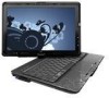
External component identification Top components Display components Item (1) Component Convertible hinge (2) Drive light (3) Battery light Function Swivels the display and converts the computer from traditional notebook mode into slate mode or vice versa. In slate mode, the display is rotated - HP Tx2-1370us | HP TouchSmart tx2 Notebook PC - Maintenance and Service Guide - Page 14
into 4 orientations: landscape primary, landscape secondary, portrait primary, and portrait secondary. (14) Consumer infrared lens Receives a signal from the HP Remote Control. *To see wireless regulatory notices, refer to the section of the Regulatory, Safety, and Environmental Notices that - HP Tx2-1370us | HP TouchSmart tx2 Notebook PC - Maintenance and Service Guide - Page 15
Keys Item (1) (2) (3) (4) (5) (6) Component esc key fn key Windows logo key Windows applications key Embedded numeric keypad keys Function keys Function Displays system information when pressed in combination with the fn key. Executes frequently used system functions when pressed in combination - HP Tx2-1370us | HP TouchSmart tx2 Notebook PC - Maintenance and Service Guide - Page 16
Pointing devices Item Component Function (1) TouchPad on/off button (2) TouchPad* (3) Left TouchPad button* (4) TouchPad light (5) TouchPad vertical scroll zone (6) Right TouchPad button* Enables/disables the TouchPad. Moves the pointer and selects or activates items on the screen. - HP Tx2-1370us | HP TouchSmart tx2 Notebook PC - Maintenance and Service Guide - Page 17
Options. To learn more about Sleep or Hibernation, refer to the Power Management guide. ● On: The computer is on. ● Blinking: The computer is in computer is off or in Hibernation. Receives a signal from the HP Remote Control. Provides enhanced audio performance, including surround sound and other - HP Tx2-1370us | HP TouchSmart tx2 Notebook PC - Maintenance and Service Guide - Page 18
are turned off. *This table describes factory settings. For information about changing factory settings, refer to the user guides located in Help and Support. Left-side components Item (1) (2) (3) Component Power connector ExpressCard slot Digital Media Slot (4) Digital Media Slot light - HP Tx2-1370us | HP TouchSmart tx2 Notebook PC - Maintenance and Service Guide - Page 19
Right-side components Item (1) Component Previous/rewind button (2) Play/pause button (3) Next/fast forward button (4) Stop button (5) Pen holder (6) USB port (7) Pen tether hole (8) RJ-45 (network) jack (9) Expansion port 3 (10) External monitor port (11) S-Video-out jack (12 - HP Tx2-1370us | HP TouchSmart tx2 Notebook PC - Maintenance and Service Guide - Page 20
Rear components Item (1) Component Vent (2) RJ-11 (modem) jack (3) USB ports (2) (4) Security cable slot Function Enables airflow to cool internal components. NOTE: The computer fan starts up automatically to cool internal components and prevent overheating. It is normal for the internal - HP Tx2-1370us | HP TouchSmart tx2 Notebook PC - Maintenance and Service Guide - Page 21
your country or region. If you replace the module and then receive a warning message, remove the module to restore computer functionality, and then contact technical support through Help and Support. Holds the battery. Bottom components 13 - HP Tx2-1370us | HP TouchSmart tx2 Notebook PC - Maintenance and Service Guide - Page 22
number (p/n): This number provides specific information about the product's hardware components. The part number helps a service technician to determine what components and parts are needed. (4) Model description: This is the number used to locate documents, drivers, and support for the computer - HP Tx2-1370us | HP TouchSmart tx2 Notebook PC - Maintenance and Service Guide - Page 23
Computer major components Item (1a) Description Display assembly 12.1-inch, WXGA, BrightView touch-screen display assembly with Web camera, fingerprint reader, microphones, and WLAN antenna cables Spare part number 504468-001 Computer major components 15 - HP Tx2-1370us | HP TouchSmart tx2 Notebook PC - Maintenance and Service Guide - Page 24
(2b) (3) (4) (5a) (5b) (6a) Description Spare part number 12.1-inch, WXGA, BrightView touch-screen display assembly with Web cover) Keyboard (includes keyboard cable) Belgium 508112-A41 Brazil 508112-201 Canada 508112-121 Denmark, Finland, and Norway 508112-DH1 France 508112-051 - HP Tx2-1370us | HP TouchSmart tx2 Notebook PC - Maintenance and Service Guide - Page 25
10) (11) (12) (13) (14) (15) (16) (17) Description Spare part number Memory module compartment cover (includes 2 captive screws, secured with C-clips) WLAN module compartment rubber feet and pen cover) 464821-001 Pen 464146-001 RTC battery 449729-001 Memory modules (DDR2, PC2-6400, 800-MHz) - HP Tx2-1370us | HP TouchSmart tx2 Notebook PC - Maintenance and Service Guide - Page 26
Item (18) Description Spare part number WLAN module Broadcom 4322 802.11a/b/g/n WLAN modules: ● For use in Canada, the Cayman Islands, Guam, Puerto and Zimbabwe Broadcom BCM4312 802.11b/g WLAN modules: ● For use in Canada, the Cayman Islands, Guam, Puerto Rico, the U.S. Virgin Islands, and - HP Tx2-1370us | HP TouchSmart tx2 Notebook PC - Maintenance and Service Guide - Page 27
Item (19) (20) Description Spare part number ● For use in Afghanistan, Albania, Algeria, Andorra, Hardware Kit (not illustrated; includes hard drive bracket, hard drive 497744-001 connector, and hard drive screws) Battery 8-cell, 73-Wh, 2.55-Ah, Li-ion 463650-003 6-cell, 55-Wh, 2.55-Ah, - HP Tx2-1370us | HP TouchSmart tx2 Notebook PC - Maintenance and Service Guide - Page 28
Plastics Kit Item (1) (2) (3) (4) (5) Description Spare part number Plastics Kit 487926-001 ExpressCard slot bezel Hard drive cover (includes 1 rubber foot and a C-clip) Memory module compartment cover (includes 2 captive screws, secured with C-clips) 20 Chapter 3 Illustrated parts catalog - HP Tx2-1370us | HP TouchSmart tx2 Notebook PC - Maintenance and Service Guide - Page 29
Mass storage devices Item (1) (2) Description Spare part number Hard drive (includes hard drive bracket, hard drive connector, and Mylar cover) 500-GB, 5400-rpm 400-GB, 5400-rpm 320-GB, 5400-rpm - HP Tx2-1370us | HP TouchSmart tx2 Notebook PC - Maintenance and Service Guide - Page 30
Miscellaneous parts Description 65-watt AC adapter HP protective sleeve HP Notebook Stand Remote control (fits into ExpressCard slot Phillips PM2.0×4.0 screws ● Phillips PM2.0×3.0 screws 22 Chapter 3 Illustrated parts catalog Spare part number 417220-001 504580-001 466337-001 465539-002 490371-D01 - HP Tx2-1370us | HP TouchSmart tx2 Notebook PC - Maintenance and Service Guide - Page 31
, and Zimbabwe 8-cell, 73-Wh, 2.55-Ah, Li-ion battery Screw Kit Pen Rubber Feet Kit (includes 4 base enclosure rubber feet and pen cover) Display Rubber Kit (includes 8 display bezel rubber screw covers) Remote control (fits into ExpressCard slot) HP Notebook Stand Sequential part number listing 23 - HP Tx2-1370us | HP TouchSmart tx2 Notebook PC - Maintenance and Service Guide - Page 32
Description Bluetooth module Broadcom 4322 802.11a/b/g/n WLAN module for use in Canada, the Cayman Islands, Guam, Puerto Rico, the U.S. Virgin Islands, and ) Plastics Kit (see Plastics Kit on page 20 for Plastics Kit spare part information) Power cord for use in North America Power cord for use in - HP Tx2-1370us | HP TouchSmart tx2 Notebook PC - Maintenance and Service Guide - Page 33
with Web camera, microphones, fingerprint reader, and WLAN antenna cables HP protective sleeve AMD Athlon Dual-Core QL-62 2.00-GHz processor bumper pads) Base enclosure (includes optical drive release assembly, 2 battery release latches, and 4 rubber feet) Pen holder and pen part number listing 25 - HP Tx2-1370us | HP TouchSmart tx2 Notebook PC - Maintenance and Service Guide - Page 34
for use in Italy Keyboard for use in Spain Keyboard for use in Switzerland Keyboard for use in Canada Keyboard for use in Portugal Keyboard for use in Turkey Keyboard for use in Latin America Keyboard for drive bracket, hard drive connector, and Mylar cover) 26 Chapter 3 Illustrated parts catalog - HP Tx2-1370us | HP TouchSmart tx2 Notebook PC - Maintenance and Service Guide - Page 35
● Flat-bladed screwdriver Service considerations The following sections include parts CAUTION: Using excessive force during disassembly and reassembly can damage plastic parts. Use care when handling the plastic parts. Apply pressure only at the points designated in the maintenance instructions - HP Tx2-1370us | HP TouchSmart tx2 Notebook PC - Maintenance and Service Guide - Page 36
Cables and connectors CAUTION: When servicing the computer, be sure that cables are placed in Be sure that cables are routed in such a way that they cannot be caught or snagged by parts being removed or replaced. Handle flex cables with extreme care; these cables tear easily. Drive handling CAUTION - HP Tx2-1370us | HP TouchSmart tx2 Notebook PC - Maintenance and Service Guide - Page 37
Grounding guidelines Electrostatic discharge damage Electronic components are sensitive to electrostatic discharge (ESD). Circuitry design and structure determine the degree of sensitivity. Networks built into many integrated circuits provide some protection, but in many cases, ESD contains enough - HP Tx2-1370us | HP TouchSmart tx2 Notebook PC - Maintenance and Service Guide - Page 38
parts and assemblies with conductive or approved containers or packaging. ● Keep ESD-sensitive parts in their containers until the parts reusable ESD-sensitive parts from assemblies in ● Use conductive field service tools, such as ● Handle ESD-sensitive components, parts, and assemblies by the case - HP Tx2-1370us | HP TouchSmart tx2 Notebook PC - Maintenance and Service Guide - Page 39
with ground cords of one megohm resistance ● Static-dissipative tables or floor mats with hard ties to the ground ● Field service kits ● Static awareness labels ● Material-handling packages ● Nonconductive plastic bags, tubes, or boxes ● Metal tote boxes ● Electrostatic voltage levels and - HP Tx2-1370us | HP TouchSmart tx2 Notebook PC - Maintenance and Service Guide - Page 40
Unknown user password If the computer you are servicing has an unknown user password, follow these steps to Remove the battery (see Battery on page 35). 5. Remove the real-time clock (RTC) battery (see RTC battery on page 39). 6. Wait approximately 5 minutes. 7. Replace the RTC battery and reassemble - HP Tx2-1370us | HP TouchSmart tx2 Notebook PC - Maintenance and Service Guide - Page 41
number (p/n): This number provides specific information about the product's hardware components. The part number helps a service technician to determine what components and parts are needed. (4) Model description: This is the number used to locate documents, drivers, and support for the computer - HP Tx2-1370us | HP TouchSmart tx2 Notebook PC - Maintenance and Service Guide - Page 42
Computer feet Description Rubber Feet Kit (includes 4 base enclosure rubber feet and pen cover) Spare part number 464821-001 The computer feet are adhesive-backed rubber pads. There are four computer feet (1) that adhere to the computer base enclosure, and two - HP Tx2-1370us | HP TouchSmart tx2 Notebook PC - Maintenance and Service Guide - Page 43
Description 8-cell, 73-Wh, 2.55-Ah, Li-ion battery 6-cell, 55-Wh, 2.55-Ah, Li-ion battery 4-cell, 37-Wh, 2.55-Ah, Li-ion battery (for use only with computer models equipped with the AMD Turion 64 processor) Spare part number 463650-003 441132-003 441131-003 Before disassembling the computer - HP Tx2-1370us | HP TouchSmart tx2 Notebook PC - Maintenance and Service Guide - Page 44
Pen Description Pen Spare part number 464146-001 Before removing the pen, follow these 2. Disconnect all external devices connected to the computer. 3. Disconnect the power cord. 4. Remove the battery (see Battery on page 35). Remove the pen: 1. Position the computer with the left side toward you. - HP Tx2-1370us | HP TouchSmart tx2 Notebook PC - Maintenance and Service Guide - Page 45
(includes hard drive bracket, hard drive connector, and hard drive screws) Spare part number 506058-001 506057-001 506056-001 519190-001 506055-001 506054-001 497744- the computer. 3. Disconnect the power cord. 4. Remove the battery (see Battery on page 35). Remove the hard drive: 1. Position the - HP Tx2-1370us | HP TouchSmart tx2 Notebook PC - Maintenance and Service Guide - Page 46
4. Remove the hard drive cover. NOTE: The hard drive cover is included in the Plastics Kit, spare part number 487926-001. 5. Grasp the Mylar tab (1) on the hard drive and lift the hard drive to disconnect it from the system board. 6. Remove the - HP Tx2-1370us | HP TouchSmart tx2 Notebook PC - Maintenance and Service Guide - Page 47
leaving it uninstalled for 5 or more minutes causes all passwords and CMOS settings to be cleared. Description RTC battery Spare part number 449729-001 Before removing the RTC battery, follow these steps: 1. Shut down the computer. If you are unsure whether the computer is off or in Hibernation - HP Tx2-1370us | HP TouchSmart tx2 Notebook PC - Maintenance and Service Guide - Page 48
LightScribe DVD±RW and CD-RW SuperMulti Double-Layer Combo Drive Spare part number 509073-001 509074-001 Before removing the optical drive, follow these to the computer. 3. Disconnect the power cord. 4. Remove the battery (see Battery on page 35). Remove the optical drive: 1. Position the computer - HP Tx2-1370us | HP TouchSmart tx2 Notebook PC - Maintenance and Service Guide - Page 49
DDR2, PC2-6400, 800-MHz) 1024-MB (DDR2, PC2-6400, 800-MHz) Spare part number 506062-001 506061-001 506060-001 Before removing the memory module, follow these steps: the computer. 3. Disconnect the power cord. 4. Remove the battery (see Battery on page 35). Remove the memory module: 1. Position the - HP Tx2-1370us | HP TouchSmart tx2 Notebook PC - Maintenance and Service Guide - Page 50
6. Pull the module (2) away from the slot at an angle and remove it. NOTE: Memory modules are designed with a notch (3) to prevent incorrect insertion into the memory module slot. Reverse this procedure to install a memory module. 42 Chapter 4 Removal and replacement procedures - HP Tx2-1370us | HP TouchSmart tx2 Notebook PC - Maintenance and Service Guide - Page 51
WLAN module Description Spare part number Broadcom 4322 802.11a/b/g/n WLAN modules: For use in Canada, the Cayman Islands, Guam, Puerto Rico Zimbabwe 487330-002 Broadcom BCM4312 802.11b/g WLAN modules: ● For use in Canada, the Cayman Islands, Guam, Puerto Rico, the U.S. Virgin Islands, and the - HP Tx2-1370us | HP TouchSmart tx2 Notebook PC - Maintenance and Service Guide - Page 52
to the computer. 3. Disconnect the power cord. 4. Remove the battery (see Battery on page 35). Remove the WLAN module: 1. Position the NOTE: The WLAN module compartment cover is included in the Plastics Kit, spare part number 487926-001. 5. Disconnect the WLAN antenna cables (1) from the WLAN module - HP Tx2-1370us | HP TouchSmart tx2 Notebook PC - Maintenance and Service Guide - Page 53
7. Pull the WLAN module (3) away from the slot at an angle and remove it. NOTE: WLAN modules are designed with a notch (4) to prevent incorrect insertion into the WLAN module slot. Reverse this procedure to install a WLAN module. Component replacement procedures 45 - HP Tx2-1370us | HP TouchSmart tx2 Notebook PC - Maintenance and Service Guide - Page 54
Description Country or region Spare part number Belgium 508112-A41 Brazil 508112-201 Canada 508112-121 Denmark, Finland, connected to the computer. 3. Disconnect the power cord. 4. Remove the battery (see Battery on page 35). Remove the keyboard: 1. Position the computer with the front - HP Tx2-1370us | HP TouchSmart tx2 Notebook PC - Maintenance and Service Guide - Page 55
4. Open the computer. 5. Lift the rear edge of the keyboard and swing it toward you until it rests on the palm rest. 6. Release the zero insertion force (ZIF) connector (1) to which the keyboard cable is attached and disconnect the keyboard cable (2). 7. Remove the keyboard. Reverse this procedure - HP Tx2-1370us | HP TouchSmart tx2 Notebook PC - Maintenance and Service Guide - Page 56
cover (includes display convertible hinge base cover) Spare part number 506827-001 Before removing the switch cover, follow devices connected to the computer. 3. Disconnect the power cord. 4. Remove the battery (see Battery on page 35). 5. Remove the keyboard (see Keyboard on page 46). Remove - HP Tx2-1370us | HP TouchSmart tx2 Notebook PC - Maintenance and Service Guide - Page 57
5. Rotate the display clockwise approximately 45 degrees. 6. Lift the left and right front corners of the switch cover (1) until it disengages from the computer. 7. Rotate the switch cover (2) counterclockwise and remove it from the computer. Reverse this procedure to install the switch cover. - HP Tx2-1370us | HP TouchSmart tx2 Notebook PC - Maintenance and Service Guide - Page 58
devices connected to the computer. 3. Disconnect the power cord. 4. Remove the battery (see Battery on page 35). 5. Remove the memory module compartment cover (see Memory module cover is included in the Plastics Kit, spare part number 487926-001. 50 Chapter 4 Removal and replacement procedures - HP Tx2-1370us | HP TouchSmart tx2 Notebook PC - Maintenance and Service Guide - Page 59
up, with the front toward you. 9. Open the computer. 10. Remove the display convertible hinge cover (1). CAUTION: Support the display assembly when removing the following screws. Failure to support the display assembly can result in damage to the display assembly and other computer components. 11 - HP Tx2-1370us | HP TouchSmart tx2 Notebook PC - Maintenance and Service Guide - Page 60
12. Disconnect the display panel cable (3) from the system board. NOTE: As you remove the display assembly, be sure that the display cables and wireless antenna cables move cleanly through the opening (1) in the computer. 13. Lift the display (2) straight up and remove it. Reverse this procedure to - HP Tx2-1370us | HP TouchSmart tx2 Notebook PC - Maintenance and Service Guide - Page 61
caps lock light board and cable, and top cover bumper pads) Spare part number 506824-001 Before removing the top cover, follow these steps: connected to the computer. 3. Disconnect the power cord. 4. Remove the battery (see Battery on page 35). 5. Remove the following components: a. Hard drive ( - HP Tx2-1370us | HP TouchSmart tx2 Notebook PC - Maintenance and Service Guide - Page 62
5. Release the ZIF connector (2) to which the TouchPad cable is connected and disconnect the TouchPad cable (3). 6. Remove the two Phillips PM2.0×4.0 screws (4) that secure the top cover to the base enclosure. 7. Lift the top cover straight up and remove it. Reverse this procedure to install the top - HP Tx2-1370us | HP TouchSmart tx2 Notebook PC - Maintenance and Service Guide - Page 63
(includes power switch board cable and actuator switch) Spare part number 506828-001 Before removing the power switch assembly, devices connected to the computer. 3. Disconnect the power cord. 4. Remove the battery (see Battery on page 35). 5. Remove the following components: a. Hard drive (see - HP Tx2-1370us | HP TouchSmart tx2 Notebook PC - Maintenance and Service Guide - Page 64
3. Remove the display release hook assembly (3). NOTE: The display release hook assemblies are included with the base enclosure spare part kit. 4. Disconnect the power switch board cable (1) from the system board. 5. Remove the power switch board (2) and power switch actuator (3) from the base - HP Tx2-1370us | HP TouchSmart tx2 Notebook PC - Maintenance and Service Guide - Page 65
Description Bluetooth module Bluetooth module cable Spare part number 483113-001 487697-001 Before removing external devices connected to the computer. 3. Disconnect the power cord. 4. Remove the battery (see Battery on page 35). 5. Remove the following components: a. Hard drive (see Hard drive - HP Tx2-1370us | HP TouchSmart tx2 Notebook PC - Maintenance and Service Guide - Page 66
board Description System board (includes replacement thermal material) Spare part number 504466-001 When replacing the system board, be on page 41) ● WLAN module (see WLAN module on page 43) ● RTC battery (see RTC battery on page 39) ● Bluetooth module (see Bluetooth module on page 57) ● Fan/heat - HP Tx2-1370us | HP TouchSmart tx2 Notebook PC - Maintenance and Service Guide - Page 67
2. Remove the ExpressCard slot bezel (2) from the ExpressCard slot. NOTE: The ExpressCard slot bezel is included in the Plastics Kit, spare part number 487926-001. 3. Release the ZIF connector (1) to which the audio/infrared board cable is connected and disconnect the audio/infrared board cable (2) - HP Tx2-1370us | HP TouchSmart tx2 Notebook PC - Maintenance and Service Guide - Page 68
5. Pull the system board (4) away from the top cover at an angle and remove it. Reverse this procedure to install the system board. 60 Chapter 4 Removal and replacement procedures - HP Tx2-1370us | HP TouchSmart tx2 Notebook PC - Maintenance and Service Guide - Page 69
Description Pen holder and pen eject assembly Spare part number 506826-001 Before removing the pen holder and all external devices connected to the computer. 3. Disconnect the power cord. 4. Remove the battery (see Battery on page 35). 5. Remove the following components: a. Pen (see Pen on page - HP Tx2-1370us | HP TouchSmart tx2 Notebook PC - Maintenance and Service Guide - Page 70
Description Audio/infrared board (includes audio/infrared board cable) Spare part number 441144-001 Before removing the audio/infrared board, follow to the computer. 3. Disconnect the power cord. 4. Remove the battery (see Battery on page 35). 5. Remove the following components: a. Hard drive - HP Tx2-1370us | HP TouchSmart tx2 Notebook PC - Maintenance and Service Guide - Page 71
i. System board (see System board on page 58) j. Pen holder (see Pen holder and pen eject assembly on page 61) Remove the audio/infrared board: 1. Remove the two Phillips PM2.0×3.0 screws (1) that secure the audio/infrared board to the system board. 2. Release the audio/infrared board (2) by sliding - HP Tx2-1370us | HP TouchSmart tx2 Notebook PC - Maintenance and Service Guide - Page 72
Description Fan/heat sink assembly (includes thermal material) Spare part number 487925-001 NOTE: To properly ventilate the computer connected to the computer. 3. Disconnect the power cord. 4. Remove the battery (see Battery on page 35). 5. Remove the following components: a. Hard drive (see - HP Tx2-1370us | HP TouchSmart tx2 Notebook PC - Maintenance and Service Guide - Page 73
(2) each time the fan/heat sink assembly is removed. Replacement thermal material is included with all system board, fan/heat sink assembly, and processor spare part kits. Reverse this procedure to install the fan/heat sink assembly. Component replacement procedures 65 - HP Tx2-1370us | HP TouchSmart tx2 Notebook PC - Maintenance and Service Guide - Page 74
kit includes replacement thermal material. Desription Spare part number AMD Turion 64 Mobile Technology Ultra external devices connected to the computer. 3. Disconnect the power cord. 4. Remove the battery (see Battery on page 35). 5. Remove the following components: a. Hard drive (see Hard drive - HP Tx2-1370us | HP TouchSmart tx2 Notebook PC - Maintenance and Service Guide - Page 75
Remove the processor: 1. Use a flat-bladed screwdriver to turn the processor locking screw (1) one-half turn counterclockwise until you hear a click. 2. Lift the processor (2) straight up and remove it. NOTE: The gold triangle (3) on the processor should be aligned with the triangle (4) embossed on - HP Tx2-1370us | HP TouchSmart tx2 Notebook PC - Maintenance and Service Guide - Page 76
5 Setup Utility WARNING! Only authorized technicians trained by HP should repair this equipment. All troubleshooting and repair procedures are detailed to allow repair at only the subassembly or module level. Because of the complexity of the individual boards and subassemblies, - HP Tx2-1370us | HP TouchSmart tx2 Notebook PC - Maintenance and Service Guide - Page 77
and exit the Setup Utility, press f10 and then follow the instructions on the screen. Your preferences go into effect when the computer the Setup Utility Because the Setup Utility is not Windows-based, it does not support the TouchPad. Navigation and selection are by keystroke. ● To choose a menu - HP Tx2-1370us | HP TouchSmart tx2 Notebook PC - Maintenance and Service Guide - Page 78
exit the Setup Utility, press f10, and then follow the instructions on the screen. The Setup Utility default settings are set Support, which is accessible only when the computer is in Windows. The Setup Utility features available for advanced users include a hard drive self-test, a Network Service - HP Tx2-1370us | HP TouchSmart tx2 Notebook PC - Maintenance and Service Guide - Page 79
then follow the instructions on the screen. supported by your computer. Main menu Select System information To do this ● View and change the system time and date. ● View identification information about the computer. ● View specification information about the processor, memory size, system BIOS - HP Tx2-1370us | HP TouchSmart tx2 Notebook PC - Maintenance and Service Guide - Page 80
Configuration menu Select Language Support Enhanced SATA support (select models only) Boot Options Button Sound (select models only) Video memory up to (select models only) Diagnostics menu Select Hard Disk Self Test Secondary Hard Disk Self Test (select models only) Memory Test To do this Change - HP Tx2-1370us | HP TouchSmart tx2 Notebook PC - Maintenance and Service Guide - Page 81
6 Specifications Computer specifications Dimensions Height (front to back) Width Depth Weight (with optical drive, hard drive, and battery) Input power Operating voltage Operating current Temperature Operating (not writing to optical disc) Operating (writing to optical disc) Nonoperating Relative - HP Tx2-1370us | HP TouchSmart tx2 Notebook PC - Maintenance and Service Guide - Page 82
thermal limits for plastic surfaces. The computer operates well within this range of temperatures. 12.1-inch, WXGA BrightView display specifications Dimensions Height Width Diagonal Number of colors Contrast ratio Brightness Pixel resolution Pitch Format Configuration Backlight Refresh rate PPI - HP Tx2-1370us | HP TouchSmart tx2 Notebook PC - Maintenance and Service Guide - Page 83
billion bytes when referring to hard drive storage capacity. Actual accessible capacity is less. †Actual drive specifications may differ slightly. NOTE: Certain restrictions and exclusions apply. Contact technical support for details. 160-GB* 9.5 mm 70 mm 102 g ATA-7 100 MB/sec ATA security 3 ms - HP Tx2-1370us | HP TouchSmart tx2 Notebook PC - Maintenance and Service Guide - Page 84
DVD±RW and CD-RW SuperMulti Double-Layer Combo Drive specifications Applicable disc Access time Random Cache buffer Data transfer rate 24X CD-ROM 8X DVD 24X CD-R 16X CD-RW 8X DVD+R /sec 5,400 KB/sec 10,800 KB/sec 5,400 KB/sec 2,700 KB/sec 6,750 KB/sec Multiword DMA Mode 76 Chapter 6 Specifications - HP Tx2-1370us | HP TouchSmart tx2 Notebook PC - Maintenance and Service Guide - Page 85
System DMA specifications Hardware DMA System function DMA0 Not applicable DMA1* Not applicable DMA2* Not applicable DMA3 Not applicable DMA4 Direct memory access controller DMA5* Available for PC Card DMA6 Not assigned DMA7 Not assigned *PC Card controller can use DMA 1, 2, or 5. - HP Tx2-1370us | HP TouchSmart tx2 Notebook PC - Maintenance and Service Guide - Page 86
System interrupt specifications Hardware IRQ System function IRQ0 IRQ1 System timer Standard 101-/102 channel *Default configuration; audio possible configurations are IRQ5, IRQ7, IRQ9, IRQ10, or none. NOTE: PC Cards may assert IRQ3, IRQ4, IRQ5, IRQ7, IRQ9, IRQ10, IRQ11, or IRQ15. Either the - HP Tx2-1370us | HP TouchSmart tx2 Notebook PC - Maintenance and Service Guide - Page 87
System I/O address specifications I/O address (hex) 000 - 00F 010 - 01F 020 - 021 022 - 024 025 - 03F 02E - 02F 040 - 05F 044 - 05F 060 Unused Secondary fixed disk controller Unused Primary fixed disk controller Unused JoyStick (decoded in ESS1688) Unused System I/O address specifications 79 - HP Tx2-1370us | HP TouchSmart tx2 Notebook PC - Maintenance and Service Guide - Page 88
Secondary diskette drive controller Parallel port (LPT1/default) Unused FM synthesizer-OPL3 Unused VGA Reserved (parallel port/no EPP support) VGA PC Card controller in CPU Unused Internal modem "A" diskette controller Serial port (COM1/default) PCI configuration index register (PCIDIVO-1) PCI - HP Tx2-1370us | HP TouchSmart tx2 Notebook PC - Maintenance and Service Guide - Page 89
00FFFFFF 04800000-07FFFFFF 04800000-07FFFFFF 08000000-080FFFFF 08200000-FFFEFFFF FFFF0000-FFFFFFFF System function Base memory Video memory Video BIOS Unused System BIOS Extended memory Super extended memory Unused Video memory (direct access) Unused System BIOS System memory map specifications 81 - HP Tx2-1370us | HP TouchSmart tx2 Notebook PC - Maintenance and Service Guide - Page 90
7 Screw listing This section provides specification and reference information for the screws and screw locks used in the computer. All screws and screw locks listed in this section are available in the Screw Kit, spare part number 464116-001. Phillips PM3.0×3.0 screw Color Silver Quantity 4 - HP Tx2-1370us | HP TouchSmart tx2 Notebook PC - Maintenance and Service Guide - Page 91
Phillips PM2.0×7.0 screw Color Black Quantity 9 Length 7.0 mm Thread 2.0 mm Head width 4.5 mm Where used: 4 screws that secure the switch cover to the computer Where used: 5 screws that secure top cover to the computer Phillips PM2.0×7.0 screw 83 - HP Tx2-1370us | HP TouchSmart tx2 Notebook PC - Maintenance and Service Guide - Page 92
Phillips PM2.0×4.0 screw Color Silver Quantity 10 Length 4.0 mm Thread 2.0 mm Head width 4.5 mm Where used: 2 screws that secure the top cover to the computer Where used: 2 screws that secure the power switch board to the base enclosure 84 Chapter 7 Screw listing - HP Tx2-1370us | HP TouchSmart tx2 Notebook PC - Maintenance and Service Guide - Page 93
Where used: 2 screws that secure the audio/infrared board to the base enclosure Where used: 4 screws that secure the fan/heat sink assembly to the system board Phillips PM2.0×4.0 screw 85 - HP Tx2-1370us | HP TouchSmart tx2 Notebook PC - Maintenance and Service Guide - Page 94
Phillips PM2.0×5.0 captive screw Color Black Quantity 6 Length 5.0 mm Thread 2.0 mm Head width 4.5 mm Where used: (1) Two captive screws (secured with C-clips) that secure the hard drive cover to the computer (2) Two captive screws (secured with C-clips) that secure the memory module - HP Tx2-1370us | HP TouchSmart tx2 Notebook PC - Maintenance and Service Guide - Page 95
Black Phillips PM2.0×3.0 screw Color Black Quantity 5 Length 3.0 mm Thread 2.0 mm Head width 4.5 mm Where used: 2 screws that secure the WLAN module to the computer Where used: 3 screws that secure the top cover to the base enclosure Black Phillips PM2.0×3.0 screw 87 - HP Tx2-1370us | HP TouchSmart tx2 Notebook PC - Maintenance and Service Guide - Page 96
Phillips PM2.0×11.0 screw Color Black Quantity 4 Length 11.0 mm Thread 2.0 mm Head width 4.5 mm Where used: 4 screws that secure the keyboard to the computer 88 Chapter 7 Screw listing - HP Tx2-1370us | HP TouchSmart tx2 Notebook PC - Maintenance and Service Guide - Page 97
Phillips PM2.5×6.0 screw Color Silver Quantity 4 Length 6.0 mm Thread 2.5 mm Head width 5.0 mm Where used: 2 screws that secure the display assembly to the computer Where used: 2 screws that secure the display assembly to the computer Phillips PM2.5×6.0 screw 89 - HP Tx2-1370us | HP TouchSmart tx2 Notebook PC - Maintenance and Service Guide - Page 98
Silver Phillips PM2.0×3.0 screw Color Silver Quantity 5 Length 3.0 mm Thread 2.0 mm Head width 4.5 mm Where used: (1) One screw that secures the display release hook to the base enclosure (2) One screw that secures the Bluetooth module to the base enclosure Where used: 3 screws that secure - HP Tx2-1370us | HP TouchSmart tx2 Notebook PC - Maintenance and Service Guide - Page 99
or driver without performing a full system recovery. ● Performing a full system recovery (Recovery Manager software feature). With Recovery DVDs store more information than CDs, DVDs and DVDs with double-layer (DL) support reduce the number of discs required. NOTE: Read-write discs, such as CD- - HP Tx2-1370us | HP TouchSmart tx2 Notebook PC - Maintenance and Service Guide - Page 100
Advanced Options. NOTE: If you are operating the computer on battery power, you will be prompted to connect to AC power before you can go to the next step. 3. Click Recovery disc creation, and then click Next. 4. Follow the on-screen instructions. Backing up your information When to back up ● On - HP Tx2-1370us | HP TouchSmart tx2 Notebook PC - Maintenance and Service Guide - Page 101
Backup suggestions ● Create a set of recovery discs using Recovery Manager. ● Create system restore points using A system restore point allows you to save and name a snapshot of your hard drive at a specific point in time. You can then recover back to that point if you want to reverse subsequent - HP Tx2-1370us | HP TouchSmart tx2 Notebook PC - Maintenance and Service Guide - Page 102
The System Protection window opens. 6. Follow the on-screen instructions. 94 Chapter 8 Backup and recovery - HP Tx2-1370us | HP TouchSmart tx2 Notebook PC - Maintenance and Service Guide - Page 103
System protection. 3. Click the System Protection tab. 4. Click the System Restore button, and then click Next. The System Restore window opens. 5. Follow the on-screen instructions. Recovering system information 95 - HP Tx2-1370us | HP TouchSmart tx2 Notebook PC - Maintenance and Service Guide - Page 104
and driver roll-back capabilities. If you have not already tried these features, try them before using Recovery Manager. NOTE: Recovery Manager computer. 3. Follow the on-screen instructions. Recovering from the partition on the hard drive You can perform a recovery from the partition on the hard - HP Tx2-1370us | HP TouchSmart tx2 Notebook PC - Maintenance and Service Guide - Page 105
9 Connector pin assignments Audio-in (microphone) Pin Signal 1 Audio signal in 2 Audio signal in 3 Ground Audio-out (headphone) Pin Signal 1 Audio out, left channel 2 Audio out, right channel 3 Ground Audio-in (microphone) 97 - HP Tx2-1370us | HP TouchSmart tx2 Notebook PC - Maintenance and Service Guide - Page 106
External monitor Pin Signal 1 Red analog 2 Green analog 3 Blue analog 4 Not connected 5 Ground 6 Ground analog 7 Ground analog 8 Ground analog 9 +5 VDC 10 Ground 11 Monitor detect 12 DDC 2B data 13 Horizontal sync 14 Vertical sync 15 DDC 2B clock 98 Chapter 9 - HP Tx2-1370us | HP TouchSmart tx2 Notebook PC - Maintenance and Service Guide - Page 107
RJ-11 (modem) Pin 1 2 3 4 5 6 RJ-45 (network) Signal Unused Tip Ring Unused Unused Unused Pin Signal 1 Transmit + 2 Transmit - 3 Receive + 4 Unused 5 Unused 6 Receive - 7 Unused 8 Unused RJ-11 (modem) 99 - HP Tx2-1370us | HP TouchSmart tx2 Notebook PC - Maintenance and Service Guide - Page 108
S-Video-out Pin Signal 1 S-VHS color (C) signal 2 Composite video signal 3 S-VHS intensity (Y) signal 4 S-VHS color ground 5 TV-CD 6 S-VHS intensity ground 7 Composite video ground Universal Serial Bus Pin Signal 1 +5 VDC 2 Data - 3 Data + 4 Ground 100 Chapter 9 Connector - HP Tx2-1370us | HP TouchSmart tx2 Notebook PC - Maintenance and Service Guide - Page 109
10 Power cord set requirements The wide range input feature of the computer permits it to operate from any line voltage from 100 to 120 volts AC or from 220 to 240 volts AC. The 3-conductor power cord set included with the computer meets the requirements for use in the country or region where the - HP Tx2-1370us | HP TouchSmart tx2 Notebook PC - Maintenance and Service Guide - Page 110
Requirements for specific countries or regions Region Accredited agency Applicable note number Australia EANSW 1 Austria OVE 1 Belgium CEBC 1 Canada CSA 2 Denmark DEMKO 1 Finland FIMKO 1 France UTE 1 Germany VDE 1 Italy IMQ 1 Japan METI 3 The Netherlands KEMA 1 - HP Tx2-1370us | HP TouchSmart tx2 Notebook PC - Maintenance and Service Guide - Page 111
11 Recycling Battery When a battery has reached the end of its useful life, do not dispose of the battery in general household waste. Follow the local laws and regulations in your area for computer battery disposal. Battery 103 - HP Tx2-1370us | HP TouchSmart tx2 Notebook PC - Maintenance and Service Guide - Page 112
exercised when removing these components. NOTE: Materials Disposal. This HP product contains mercury in the backlight in the display assembly that NOTE: The procedures provided in this chapter are general disassembly instructions. Specific details, such as screw sizes, quantities, and locations, and - HP Tx2-1370us | HP TouchSmart tx2 Notebook PC - Maintenance and Service Guide - Page 113
3. Remove the display bezel (3). 4. Disconnect all display panel cables (1) from the display inverter and remove the inverter (2). 5. Remove all screws (1) that secure the display panel assembly to the display enclosure. 6. Remove the display panel assembly (2) from the display enclosure. 7. Turn - HP Tx2-1370us | HP TouchSmart tx2 Notebook PC - Maintenance and Service Guide - Page 114
8. Remove all screws that secure the display panel frame to the display panel. 9. Use a sharp-edged tool to cut the tape (1) that secures the sides of the display panel to the display panel frame. 10. Remove the display panel frame (2) from the display panel. 11. Remove the screws (1) that secure - HP Tx2-1370us | HP TouchSmart tx2 Notebook PC - Maintenance and Service Guide - Page 115
15. Remove the backlight cables (1) from the clip (2) in the display panel. 16. Turn the display panel upside down. 17. Remove the backlight frame from the display panel. WARNING! The backlight contains mercury. Exercise caution when removing and handling the backlight to avoid damaging this - HP Tx2-1370us | HP TouchSmart tx2 Notebook PC - Maintenance and Service Guide - Page 116
19. Disconnect the display cable (1) from the LCD panel. 20. Remove the screws (2) that secure the LCD panel to the display rear panel. 21. Release the LCD panel (3) from the display rear panel. 22. Release the tape (4) that secures the LCD panel to the display rear panel. 23. Remove the LCD panel. - HP Tx2-1370us | HP TouchSmart tx2 Notebook PC - Maintenance and Service Guide - Page 117
part number 17, 23, 62 B backup 92 base enclosure, spare part number 17, 25 battery removal 35 spare part numbers 19, 23, 35 battery bay 13 battery light 5 battery release latch 13 Bluetooth module removal 57 spare part locations 34 spare part number 17, 23, 34 computer specifications 73 connector - HP Tx2-1370us | HP TouchSmart tx2 Notebook PC - Maintenance and Service Guide - Page 118
7 Windows logo 7 L language support 69, 72 left-side components 10 lights battery 5 Digital Media Slot 10 drive 5 optical drive release 10 power 6, 9 wireless 10 M Main menu 71 mass storage devices, spare part numbers 21 MediaSmart button 6 memory map specifications 81 memory module product - HP Tx2-1370us | HP TouchSmart tx2 Notebook PC - Maintenance and Service Guide - Page 119
3 ports 3 power requirements 3 processors 1 product name 1 security 3 serviceability 3 wireless 2 product name 1 protective sleeve, spare part number 22, 25 R rear components 12 recovery discs 91 recovery, system 91, 96 remote control, spare part number 22, 23 removal/replacement preliminaries 27 - HP Tx2-1370us | HP TouchSmart tx2 Notebook PC - Maintenance and Service Guide - Page 120
ExpressCard 10 software, safeguarding information 91 specifications computer 73 display 74 DVD±RW part number 17, 25, 58 System Configuration menu 72 system DMA 77 system information 69, 71 system memory map 81 system recovery 91 system restore points 93 TouchPad right button 8 TouchPad scroll zone - HP Tx2-1370us | HP TouchSmart tx2 Notebook PC - Maintenance and Service Guide - Page 121
-
 1
1 -
 2
2 -
 3
3 -
 4
4 -
 5
5 -
 6
6 -
 7
7 -
8
-
9
-
10
-
11
-
12
-
13
-
14
-
15
-
16
-
17
-
18
-
19
-
20
-
21
-
22
-
23
-
24
-
25
-
26
-
27
-
28
-
29
-
30
-
31
-
32
-
33
-
34
-
35
-
36
-
37
-
38
-
39
-
40
-
41
-
42
-
43
-
44
-
45
-
46
-
47
-
48
-
49
-
50
-
51
-
52
-
53
-
54
-
55
-
56
-
57
-
58
-
59
-
60
-
61
-
62
-
63
-
64
-
65
-
66
-
67
-
68
-
69
-
70
-
71
-
72
-
73
-
74
-
75
-
76
-
77
-
78
-
79
-
80
-
81
-
82
-
83
-
84
-
85
-
86
-
87
-
88
-
89
-
90
-
91
-
92
-
93
-
94
-
95
-
96
-
97
-
98
-
99
-
100
-
101
-
102
-
103
-
104
-
105
-
106
-
107
-
108
-
109
-
110
-
111
-
112
-
113
-
114
-
115
-
116
-
117
-
118
-
119
-
120
-
121
 |
 |

HP TouchSmart tx2 Notebook PC
Maintenance and Service Guide