HP Tx2-1370us HP TouchSmart tx2 Notebook PC - Maintenance and Service Guide - Page 63
Power switch assembly, Remove the Phillips PM2.0×3.0 screw
 |
UPC - 884962549247
View all HP Tx2-1370us manuals
Add to My Manuals
Save this manual to your list of manuals |
Page 63 highlights
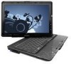
Power switch assembly Description Power switch assembly (includes power switch board cable and actuator switch) Spare part number 506828-001 Before removing the power switch assembly, follow these steps: 1. Shut down the computer. If you are unsure whether the computer is off or in Hibernation, turn the computer on, and then shut it down through the operating system. 2. Disconnect all external devices connected to the computer. 3. Disconnect the power cord. 4. Remove the battery (see Battery on page 35). 5. Remove the following components: a. Hard drive (see Hard drive on page 37) b. Optical drive (see Optical drive on page 40) c. Keyboard (see Keyboard on page 46) d. Switch cover (see Switch cover on page 48) e. Display assembly (see Display assembly on page 50) f. Top cover (see Top cover on page 53) Remove the power switch assembly: 1. Remove the two Phillips PM2.0×4.0 screws (1) that secure the power switch board to the base enclosure. 2. Remove the Phillips PM2.0×3.0 screw (2) that secures the display release hook assembly to the base enclosure. Component replacement procedures 55
-
 1
1 -
2
-
3
-
4
-
5
-
6
-
7
-
8
-
9
-
10
-
11
-
12
-
13
-
14
-
15
-
16
-
17
-
18
-
19
-
20
-
21
-
22
-
23
-
24
-
25
-
26
-
27
-
28
-
29
-
30
-
31
-
32
-
33
-
34
-
35
-
36
-
37
-
38
-
39
-
40
-
41
-
42
-
43
-
44
-
45
-
46
-
47
-
48
-
49
-
50
-
51
-
52
-
53
-
54
-
55
-
56
-
57
-
 58
58 -
 59
59 -
 60
60 -
 61
61 -
 62
62 -
 63
63 -
 64
64 -
 65
65 -
 66
66 -
 67
67 -
 68
68 -
69
-
70
-
71
-
72
-
73
-
74
-
75
-
76
-
77
-
78
-
79
-
80
-
81
-
82
-
83
-
84
-
85
-
86
-
87
-
88
-
89
-
90
-
91
-
92
-
93
-
94
-
95
-
96
-
97
-
98
-
99
-
100
-
101
-
102
-
103
-
104
-
105
-
106
-
107
-
108
-
109
-
110
-
111
-
112
-
113
-
114
-
115
-
116
-
117
-
118
-
119
-
120
-
121
 |
 |
