HP Workstation x4000 hp workstation x4000 - Technical Reference manual - Windo - Page 214
Understanding the Diag LEDs, The BIOS is in Boot Block Recovery
 |
View all HP Workstation x4000 manuals
Add to My Manuals
Save this manual to your list of manuals |
Page 214 highlights
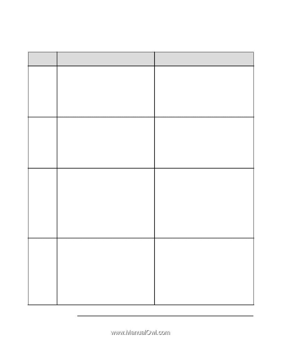
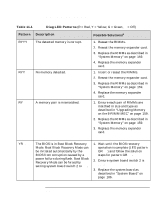
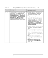
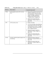
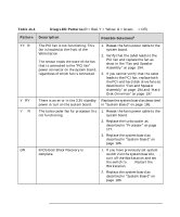
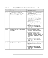
Troubleshooting Understanding the Diag LEDs Table 11-1 Diag LED Patterns (R = Red, Y = Yellow, G = Green, q = Off) Pattern Description Possible Solutionsa RYYY The detected memory is corrupt. RYYq No memory detected. RYqq A memory pair is mismatched. 1. Reseat the RIMMs. 2. Reseat the memory expander card. 3. Replace the RIMMs as described in "System Memory" on page 159. 4. Replace the memory expander card. 1. Insert or reseat the RIMMs. 2. Reseat the memory expander card. 3. Replace the RIMMs as described in "System Memory" on page 159. 4. Replace the memory expander card. 1. Ensure each pair of RIMMs are matched in size and type as described in "Upgrading Memory on the 8-RIMM MEC" on page 159. 2. Replace the RIMMs as described in "System Memory" on page 159. 3. Replace the memory expander card. YRqq The BIOS is in Boot Block Recovery Mode. Boot Block Recovery Mode can be initiated automatically by the BIOS from corruption caused by a power failure during flash. Boot Block Recovery Mode can be forced by setting system board switch 2 to ON. 1. Wait until the BIOS recovery operation is complete (LED pattern GRqq) and follow the solution steps for pattern GRqq. 2. Ensure system board switch 2 is OFF. 3. Replace the system board as described in "System Board" on page 186. 214 Chapter 11
-
 1
1 -
2
-
3
-
4
-
5
-
6
-
7
-
8
-
9
-
10
-
11
-
12
-
13
-
14
-
15
-
16
-
17
-
18
-
19
-
20
-
21
-
22
-
23
-
24
-
25
-
26
-
27
-
28
-
29
-
30
-
31
-
32
-
33
-
34
-
35
-
36
-
37
-
38
-
39
-
40
-
41
-
42
-
43
-
44
-
45
-
46
-
47
-
48
-
49
-
50
-
51
-
52
-
53
-
54
-
55
-
56
-
57
-
58
-
59
-
60
-
61
-
62
-
63
-
64
-
65
-
66
-
67
-
68
-
69
-
70
-
71
-
72
-
73
-
74
-
75
-
76
-
77
-
78
-
79
-
80
-
81
-
82
-
83
-
84
-
85
-
86
-
87
-
88
-
89
-
90
-
91
-
92
-
93
-
94
-
95
-
96
-
97
-
98
-
99
-
100
-
101
-
102
-
103
-
104
-
105
-
106
-
107
-
108
-
109
-
110
-
111
-
112
-
113
-
114
-
115
-
116
-
117
-
118
-
119
-
120
-
121
-
122
-
123
-
124
-
125
-
126
-
127
-
128
-
129
-
130
-
131
-
132
-
133
-
134
-
135
-
136
-
137
-
138
-
139
-
140
-
141
-
142
-
143
-
144
-
145
-
146
-
147
-
148
-
149
-
150
-
151
-
152
-
153
-
154
-
155
-
156
-
157
-
158
-
159
-
160
-
161
-
162
-
163
-
164
-
165
-
166
-
167
-
168
-
169
-
170
-
171
-
172
-
173
-
174
-
175
-
176
-
177
-
178
-
179
-
180
-
181
-
182
-
183
-
184
-
185
-
186
-
187
-
188
-
189
-
190
-
191
-
192
-
193
-
194
-
195
-
196
-
197
-
198
-
199
-
200
-
201
-
202
-
203
-
204
-
205
-
206
-
207
-
208
-
 209
209 -
 210
210 -
 211
211 -
 212
212 -
 213
213 -
 214
214 -
 215
215 -
 216
216 -
 217
217 -
 218
218 -
 219
219 -
220
-
221
-
222
-
223
-
224
-
225
-
226
-
227
-
228
-
229
-
230
-
231
-
232
-
233
-
234
-
235
-
236
-
237
-
238
 |
 |