Hitachi HDS722512VLAT20 Product Brief - Page 2
Hitachi Global Storage Technologies - jumper settings
 |
View all Hitachi HDS722512VLAT20 manuals
Add to My Manuals
Save this manual to your list of manuals |
Page 2 highlights
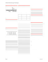
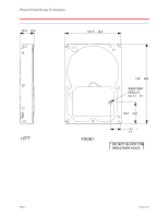
Hitachi Global Storage Technologies Connectors Pin 1 Pin A AT I/F Connector Jumper Power Block Connector The DC power connector is designed to mate with AMP p/n 1-80424-0 using AMP strip pins (p/n 350078-4), loose piece pins (p/n 61173-4), or their equivalents. Note: The AT signal connector is a 40-pin connector. Cabling The length of the cable from the host system to the drive must not exceed 18 inches. For systems operating with Ultra DMA mode 3, 4, or 5, the 80-conductor ATA cable assembly must be used. Jumper block Jumper pin letter designations I GECA H F DB A jumper attaches two pins together to configure the drive for the proper mode of operation. Jumper settings 16 head logical architecture Master active* A-B and G-H Slave active A-B and C-D Cable Select A-B and E-F Master/Slave present E-F and G-H Reserved I 15 head logical architecture Master active A-C and G-H Slave active A-C Cable select A-C and E-F Master/Slave present A-C, E-F & G-H Reserved I All other jumper settings are reserved. Do not make other settings! *Shipping default DC power requirements Damage to the drive electronics may result if the power supply cable is connected or disconnected while the power is on. There is no special power on/off sequencing required. The following voltage specification is applied at the power connector of the drive. Input voltage (Volts) +5 During run and Absolute spin up max spike (Volts) voltage 5 ± 5% 1 7 +12 12 +10% -8% 1 15 1Power supply voltage spikes in excess of the maximum values specified in the table may damage the drive electronics. Power supply current mA RMS +5 V +12V Total Watts 250 GB model Idle avg 280 470 7.0 Idle ripple - peak to peak 230 330 - Seek peak 590 1950 - Seek avg 1 330 690 10.0 Start up-max 870 1840 - RND R/W peak 790 1800 - RND R/W avg2 490 660 10.3 Standby avg 140 20 0.9 Sleep avg 100 20 0.7 120 GB and 160 GB model Idle avg 280 375 5.9 Idle ripple - p to p 230 250 - Seek peak 590 1790 - Seek avg 1 330 610 6.7 Start up-max 740 1800 - RND R/W peak RND R/W avg2 1252 1600 430 590 10.1 Standby avg 140 20 0.9 Sleep avg 100 20 0.7 40 GB and 80 GB model Idle avg 280 300 5.0 Idle ripple - p to p 230 220 - Seek peak 600 1550 - Seek avg 1 330 520 7.9 Start up-max 870 1700 - RND R/W peak 1252 1720 - RND R/W avg2 430 590 8.3 Standby avg 140 20 0.9 Sleep avg 100 20 0.7 1 Random seeks at 40% duty cycle 2 Seek duty = 30%, W/R duty = 45%, Idle Duty = 25% Power supply generated ripple Output (V) +5 +12 Maximum (mV p-p) 100 150 Freq. range (MHz) 0-10 0-10 Hot Plug/Unplug support Hot plugging/unplugging is not allowed. Damage to the drive electronics may result if the power supply cable is connected or disconnected while power is being applied to the drive. Data organization (logical) Number of heads Sectors/track Number of cylinders 16 63 16,383 Capacity (GB) 40 80 120 160 250 Total logical data bytes 41,174,178,880 82,348,277,760 123,522,416,640 164,696,555,520 250,059,350,016 Electromagnetic compatibility When installed in a suitable enclosure and exercised with a random accessing routine at the maximum data rate the hard disk drive meets the following worldwide EMC requirements listed below: • United States Federal Communications Commission (FCC) Rules and Regulations (Class B), Part 15. • European Economic Community (EEC) directive number 76/889 related to the control of radio frequency interference and the Verband Deutscher Elektrotechniker (VDE) requirements of Germany (GOP). Page 2 version 1.0
-
 1
1 -
 2
2 -
 3
3 -
 4
4 -
 5
5 -
 6
6 -
 7
7
 |
 |
