Homelite UT46510 User Manual - Page 12
Features, Assembly
 |
View all Homelite UT46510 manuals
Add to My Manuals
Save this manual to your list of manuals |
Page 12 highlights
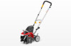
FEATURES PRODUCT SPECIFICATIONS Input...120 V, 60 Hz, AC only, 8.5 Amps Weight...28.5 lbs. KNOW YOUR CULTIVATOR See Figure 2. The safe use of this product requires an understanding of the information on the tool and in this operator's manual as well as a knowledge of the project you are attempting. Before use of this product, familiarize yourself with all operating features and safety rules. SWITCH LOCK-OUT The switch lock-out prevents accidental starting of the cultivator. SWITCH TRIGGER The switch trigger starts and stops the rotation of the tines. ASSEMBLY UNPACKING This product requires assembly. n Carefully remove the tool and any accessories from the box. Make sure that all items listed in the packing list are included. WARNING: This new product has been shipped in a partially assembled condition as described below. Carefully check the packing list below to ensure all items are included in the package; the packing list describes all loose items that are not assembled to the product as shipped. Do not operate the product if any packing list items are already assembled to your product when you unpack it. Call the customer service number below for assistance. Operation of a product that may have been improperly preassembled could result in serious personal injury. n Inspect the tool carefully to make sure no breakage or damage occurred during shipping. n Do not discard the packing material until you have carefully inspected and satisfactorily operated the tool. n If any parts are damaged or missing, please call 1-800-242-4672 for assistance. PACKING LIST Cultivator Drag stake Adjustment Knob Hitch Pins (2) Felt Washers (2) Inner Tines (2) Outer Tines (2) Wheels (2) Wheel Washers (2) PACKING LIST (continued) Wheel Hitch Pins (2) Front Handle Handlebar Bolts (2) Knobs (2) Operator's Manual WARNING: If any parts are damaged or missing do not operate this tool until the parts are replaced. Use of this product with damaged or missing parts could result in serious personal injury. WARNING: Do not attempt to modify this tool or create accessories not recommended for use with this tool. Any such alteration or modification is misuse and could result in a hazardous condition leading to possible serious personal injury. WARNING: Do not connect to power supply until assembly is complete. Failure to comply could result in accidental starting and possible serious personal injury. ASSEMBLING THE HANDLEBAR See Figure 3. n Loosen the two handlebar knobs. n Unfold the handlebar into operating position. NOTE: Do not use force. If there is binding, continue to loosen the knobs. Do not allow the switch cable to become pinched when raising the handlebar. n Retighten the handlebar knobs. Page 8 - English
-
 1
1 -
2
-
3
-
4
-
5
-
6
-
 7
7 -
 8
8 -
 9
9 -
 10
10 -
 11
11 -
 12
12 -
 13
13 -
 14
14 -
 15
15 -
 16
16 -
 17
17 -
18
-
19
-
20
-
21
-
22
-
23
-
24
-
25
-
26
-
27
-
28
-
29
-
30
-
31
-
32
-
33
-
34
-
35
-
36
-
37
-
38
-
39
-
40
 |
 |
