Honeywell CT2400 Owner's Manual - Page 7
Adjust Fan Operation Switch, As Required, Adjust System On-Time, As Required - install
 |
View all Honeywell CT2400 manuals
Add to My Manuals
Save this manual to your list of manuals |
Page 7 highlights
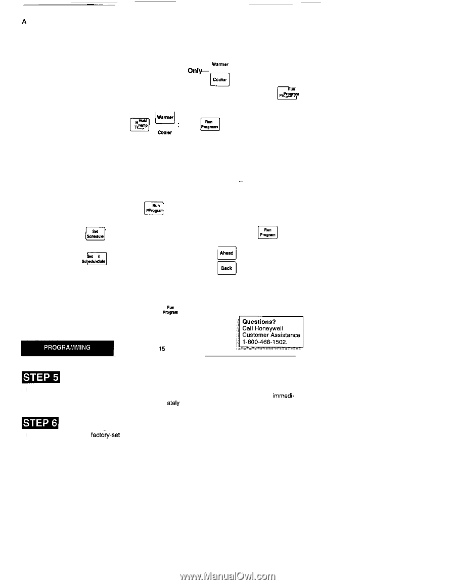
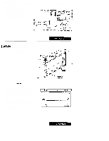
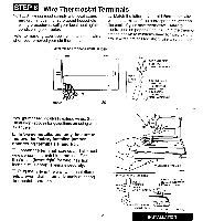
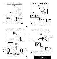
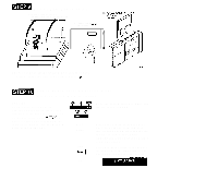
--. A quick guide for operating or making changes follows: NOTE: System switch must be set to Heat or Cool to perform the following: Temp u- Warmer Temporarily Change Temperature for Current Period Only- . Temporary indicator will Cmlar n show on display; it will cancel itself at next scheduled change. To cancel sooner, press P~& o Temp Warmaf n ; Hold a Temperature Indefinitely- ~~~P , u press pJ& to cancel. 0 0 Coobr 14 - - - .- . n Check Current Temperature Setting- p;~~m . (If using Temporarily Change or Hold, pressing this will cancel your change.) D Check Programs- ~~Uk repeatedly to see each time and temperature; Time then Pro ogRruan m . (1 c1 Cancel a Program- ~~~Ub until program to cancel shows; then H together. Beck o Permanently Change a Program-Repeat steps under Heating Program or Cooling Program (pages 12 and 13) as applicable. u Return to normal program or start program - p;~~m . ~ : Customem r Assistance _ Adjust Fan Operation Switch, As Required D The thermostat fan operation switch, labeled FUEL SWITCH (see illustration on page 17) is factory-set in the "F position. This is the correct setting for most systems. If your system is an electric heat system, set the switch to "E. The "E setting will allow the fan to turn on immedi- ately with the heating or cooling in a system where the "G" terminal is connected. _ Adjust System On-Time, As Required El The system on-time is facto-~-set for a warm air, gas or oil heating system. If you are installing it on another type of system, the system on-time must be adjusted accordingly by setting screws A and B on the back of the thermostat. Use the heating system table shown in the illustration, (page 17) as a guide. The system on-time should be optimized according to the type of system to minimize room temperature swings. Setting the screw "out one turn" means turning the screw approximately 360° counterclockwise, or about one complete turn. In the unlikely event that you want longer furnace on-time, readjust screws A and/or B as follows: First, turn both screws in completely, then adjust for system type: q Warm Air Furnace-Set at the Hot Water setting, (A - out one turn, B - in). q Electric Furnace-Leave at the Warm Air Furnace setting (A - in, B - in). 16
-
 1
1 -
 2
2 -
 3
3 -
 4
4 -
 5
5 -
 6
6 -
 7
7 -
 8
8 -
 9
9 -
 10
10 -
 11
11 -
 12
12 -
13
-
14
 |
 |