Honeywell CT3455 Owner's Manual - Page 13
Wallplate Terminals
 |
View all Honeywell CT3455 manuals
Add to My Manuals
Save this manual to your list of manuals |
Page 13 highlights
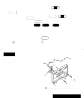
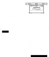
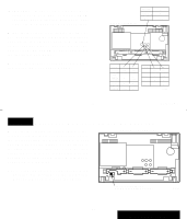
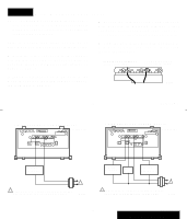
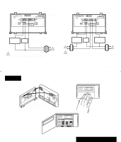
STEP 8 Wire Wallplate Terminals NOTE: All wiring must comply with local codes and ordinances. If unsure about household wiring procedures, call your local heating/air conditioning contractor. s Loosen the terminal screws and slip each wire beneath its matching terminal. Either straight or wraparound wiring connections are acceptable (see illustration). Tighten terminals. Refer to masking tape labels you placed on wires when you removed your old thermostat. s Match the letter of your old thermostat wire with the terminal of the corresponding letter on your new thermostat. Refer to illustrations on pages 22 and 23. s Plug the hole in the wall with insulation to help prevent drafts from adversely affecting thermostat operation. FOR STRAIGHT INSERTION- STRIP 5/16 IN. (8MM) FOR WRAPAROUND- STRIP 7/16 IN. (11MM) In 5-wire installations only, be sure to re- move the factory-installed jumper connect- M2486 ing terminals R and Rc. 21 69-0733-3 2-WIRE HEAT-ONLY (JUMPER INTACT) W G R RC Y THERMOSTAT 4-WIRE HEAT/COOL (JUMPER INTACT) W G R RC Y THERMOSTAT HEATING RELAY OR VALVE COIL 1 1 POWER SUPPLY. PROVIDE DISCONNECT MEANS AND OVERLOAD PROTECTION AS REQUIRED. M612A HEATING RELAY OR VALVE COIL FAN RELAY COOLING CONTACTOR COIL 1 1 POWER SUPPLY. PROVIDE DISCONNECT MEANS AND OVERLOAD PROTECTION AS REQUIRED. M614A 22 69-0733-3 INSTALLATION
-
 1
1 -
2
-
3
-
4
-
5
-
6
-
7
-
 8
8 -
 9
9 -
 10
10 -
 11
11 -
 12
12 -
 13
13 -
 14
14 -
 15
15 -
 16
16 -
 17
17 -
 18
18 -
19
-
20
 |
 |
