Honeywell T7351F2010 Installation Instructions
Honeywell T7351F2010 - Digital Thermostat, 3h Manual
 |
View all Honeywell T7351F2010 manuals
Add to My Manuals
Save this manual to your list of manuals |
Honeywell T7351F2010 manual content summary:
- Honeywell T7351F2010 | Installation Instructions - Page 1
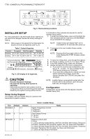
conditions, install the thermostat in an area that is accessible for setting and adjusting the temperature and settings. Install the remote-mounted sensor(s) about 5 ft. (1.5m) above the floor in an area with good air circulation at average temperature (See Fig. 1). If multiple remote sensors are - Honeywell T7351F2010 | Installation Instructions - Page 2
T7351 COMMERCIAL PROGRAMMABLE THERMOSTAT Mounting Subbase The subbase mounts horizontally. IMPORTANT • When using the internal temperature or humidity sensor, the device must be mounted horizontally (with the LCD facing upwards). Precise leveling is not needed. • When using remote room temperature - Honeywell T7351F2010 | Installation Instructions - Page 3
T7351 COMMERCIAL PROGRAMMABLE THERMOSTAT Wiring Follow equipment manufacturer wiring instructions when available. Refer to the is a call for heating or cooling. Not Occupied No Sensor Wired Not Occupied Fan On Fan Offa Occupancy sensor will only be active during Not Occupied Motion Sensed Not - Honeywell T7351F2010 | Installation Instructions - Page 4
COMMERCIAL PROGRAMMABLE THERMOSTAT Occupied HEAT Temperature COOL Not Occupied HEAT COOL Set Day/Time Day Time Override Temporary Temporary Occupied Not Occupied Schedule Clear System Fan Run Day Occupied Not Occupied Start Time Copy HEAT COOL ON AUTO Schedule Fig. 5. Thermostat - Honeywell T7351F2010 | Installation Instructions - Page 5
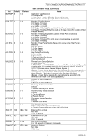
T7351 COMMERCIAL PROGRAMMABLE THERMOSTAT Text Default Installer Remote Sensor, No Remote Setpoint, Bypass 0) 2: TR22/TR23 and T7770B/C (Remote Sensor, Remote Setpoint, Bypass 0) 3: T7771 (Remote sensor, Remote Setpoint, Bypass 1) (Bypass 0 means that by pressing the override button the thermostat - Honeywell T7351F2010 | Installation Instructions - Page 6
T7351 COMMERCIAL PROGRAMMABLE THERMOSTAT Table 3. Installer Setup. (Continued) Text Default Choices Notes TMP Sensor is Selected) NO: None YES: Enabled Cooling Lockout Temperature (Display only if Remote Outdoor Air Sensor is configured) Discharge Low Limit (Only displayed if Discharge Air Sensor - Honeywell T7351F2010 | Installation Instructions - Page 7
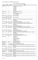
COMMERCIAL PROGRAMMABLE THERMOSTAT Text Default Choices DSTMON1 3 DSTDAY1 40 0 - 12 0 - 31, 32 - 74 DSTMON2 11 DSTDAY2 33 0 - 12 0 - 31, 32 - 74 HT RESP 1 0 - 3 CL RESP 0 0 - 1 Table 3. Installer of up to 99 days. To enable this function, the user must set the date: 1. Press Set Day and Set - Honeywell T7351F2010 | Installation Instructions - Page 8
T7351 COMMERCIAL PROGRAMMABLE THERMOSTAT Grouping Temperature Set Override Schedule Table 5. T7351 increments. Temporary occupied setting for length of time defined by installer. User can modify setpoints. Sets holiday length. User selects number of days ("0"-"99"), or "---" for continuous - Honeywell T7351F2010 | Installation Instructions - Page 9
T7351 COMMERCIAL PROGRAMMABLE THERMOSTAT Test Mode (Occupied/Not Occupied/ Schedule Day) CAUTION the above process. The system test times out after ten minutes with no key pressed. Save User Schedule (Info/Copy) Performing this operation saves the current schedule (including holidays) to memory, - Honeywell T7351F2010 | Installation Instructions - Page 10
T7351 COMMERCIAL PROGRAMMABLE THERMOSTAT Dehumid Hot Gas BP The auxiliary output operates as shown in Table 6. Table 6. Hot Gas Bypass Dehumidification Logic. Humidity Cooling Stages Active Auxiliary Output High - Honeywell T7351F2010 | Installation Instructions - Page 11
WIRING DIAGRAMS T7351 COMMERCIAL PROGRAMMABLE THERMOSTAT GND SENSOR SET PT LED BYPASS TR23-H REMOTE SENSOR 1 2 3 4 5 6 7 8 9 10 11 12 OUTDOOR AIR SENSOR DISCHARGE AIR SENSOR COMPRESSOR CONTACTOR 2 AUX HEAT STAGE 1 SUBBASE T5 T6 T7 T4 T3 OS OS AS AS W2 W1 Y2 4 HS HC HP M M X RH RC AUX O/B - Honeywell T7351F2010 | Installation Instructions - Page 12
T7351 COMMERCIAL PROGRAMMABLE THERMOSTAT GND SENSOR SET PT LED BYPASS TR23-H REMOTE SENSOR 1 2 3 4 5 6 7 8 9 10 11 12 OUTDOOR AIR SENSOR DISCHARGE AIR SENSOR HEAT RELAY 3 COMPRESSOR CONTACTOR 2 HEAT RELAY 2 SUBBASE T5 T6 T7 T4 T3 OS OS AS AS W3/Y4 Y3 W2 Y2 5 HS HC HP M M X RH - Honeywell T7351F2010 | Installation Instructions - Page 13
T7351 COMMERCIAL PROGRAMMABLE THERMOSTAT Table 7. Troubleshooting Information. (Continued) Symptom Possible Cause Action Heat will not come on. Cooling will not come on. No power to the thermostat. Check that X terminal is connected to the system transformer. Check for 24 Vac between X and RH - Honeywell T7351F2010 | Installation Instructions - Page 14
T7351 COMMERCIAL PROGRAMMABLE THERMOSTAT 62-0258-05 14 - Honeywell T7351F2010 | Installation Instructions - Page 15
T7351 COMMERCIAL PROGRAMMABLE THERMOSTAT 15 62-0258-05 - Honeywell T7351F2010 | Installation Instructions - Page 16
T7351 COMMERCIAL PROGRAMMABLE THERMOSTAT Automation and Control Solutions Honeywell International Inc. 1985 Douglas Drive North Golden Valley, MN 55422 Honeywell Limited-Honeywell Limitée 35 Dynamic Drive Toronto, Ontario M1V 4Z9 customer.honeywell.com ® U.S. Registered Trademark © 2010 Honeywell
-
 1
1 -
 2
2 -
 3
3 -
 4
4 -
 5
5 -
 6
6 -
 7
7 -
8
-
9
-
10
-
11
-
12
-
13
-
14
-
15
-
16
 |
 |
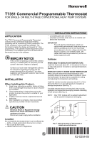
INSTALLATION INSTRUCTIONS
Place Bar Code Here
62-0258-05
T7351 Commercial Programmable Thermostat
FOR SINGLE- OR MULTI-STAGE CONVENTIONAL/HEAT PUMP SYSTEMS
APPLICATION
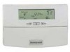
The T7351 Commercial Programmable Thermostat
controls 24 Vac commercial single zone heating,
ventilating and air conditioning (HVAC) equipment. The
T7351 consists of a thermostat and subbase. The
thermostat includes the display and keypad for 7-day
programming. The subbase includes equipment control
connections. The subbase mounts on the wall and the
thermostat mounts to the subbase.
MERCURY NOTICE
If this control is replacing a control that contains
mercury in a sealed tube, do not place your old
control in the trash. Dispose of properly.
Contact your local waste management authority
for instructions regarding recycling and the
proper disposal of an old control. If you have
questions, call Honeywell Customer Care Center
at 1-800-468-1502.
INSTALLATION
When Installing this Product...
1.
Read these instructions carefully. Failure to follow
them could damage the product or cause a hazard-
ous condition.
2.
Check ratings given in instructions and on the
product to ensure the product is suitable for your
application.
3.
Installer must be a trained, experienced service
technician.
4.
After installation is complete, check out product
operation as provided in these instructions.
CAUTION
Electrical Shock or Equipment Damage
Hazard. Can shock individuals or short
equipment circuitry.
Disconnect power supply before installation.
Location
Do not install the thermostat where it can be affected by:
— drafts, or dead spots behind doors and in corners.
— hot or cold air from ducts.
— radiant heat from sun or appliances.
— concealed pipes and chimneys.
— unheated (uncooled) areas such as an outside wall
behind the thermostat.
IMPORTANT
To avoid electrical interference, which can
cause erratic performances, keep wiring runs as
short as possible and do not run thermostat
wires adjacent to the line voltage electrical dis-
tribution systems. Use shielded cable. The
cable shield must be grounded only at the con-
trolled equipment case.
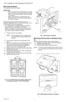
Subbase
WHEN USED TO SENSE ROOM TEMPERATURE
Install the thermostat about 5 ft. (1.5m) above the floor in
an area with good air circulation at average temperature.
(See Fig. 1.)
WHEN NOT USED TO SENSE ROOM TEMPERATURE
When using the remote-mounted temperature (and
humidity) sensor(s) to sense ambient conditions, install
the thermostat in an area that is accessible for setting
and adjusting the temperature and settings.
Install the remote-mounted sensor(s) about 5 ft. (1.5m)
above the floor in an area with good air circulation at
average temperature (See Fig. 1).
If multiple remote sensors are required, they must be
arranged in a temperature averaging network consisting
of four sensors (See Fig. 2).
NOTE:
Only TR21 models with no setpoint adjustment
can be used for temperature averaging.
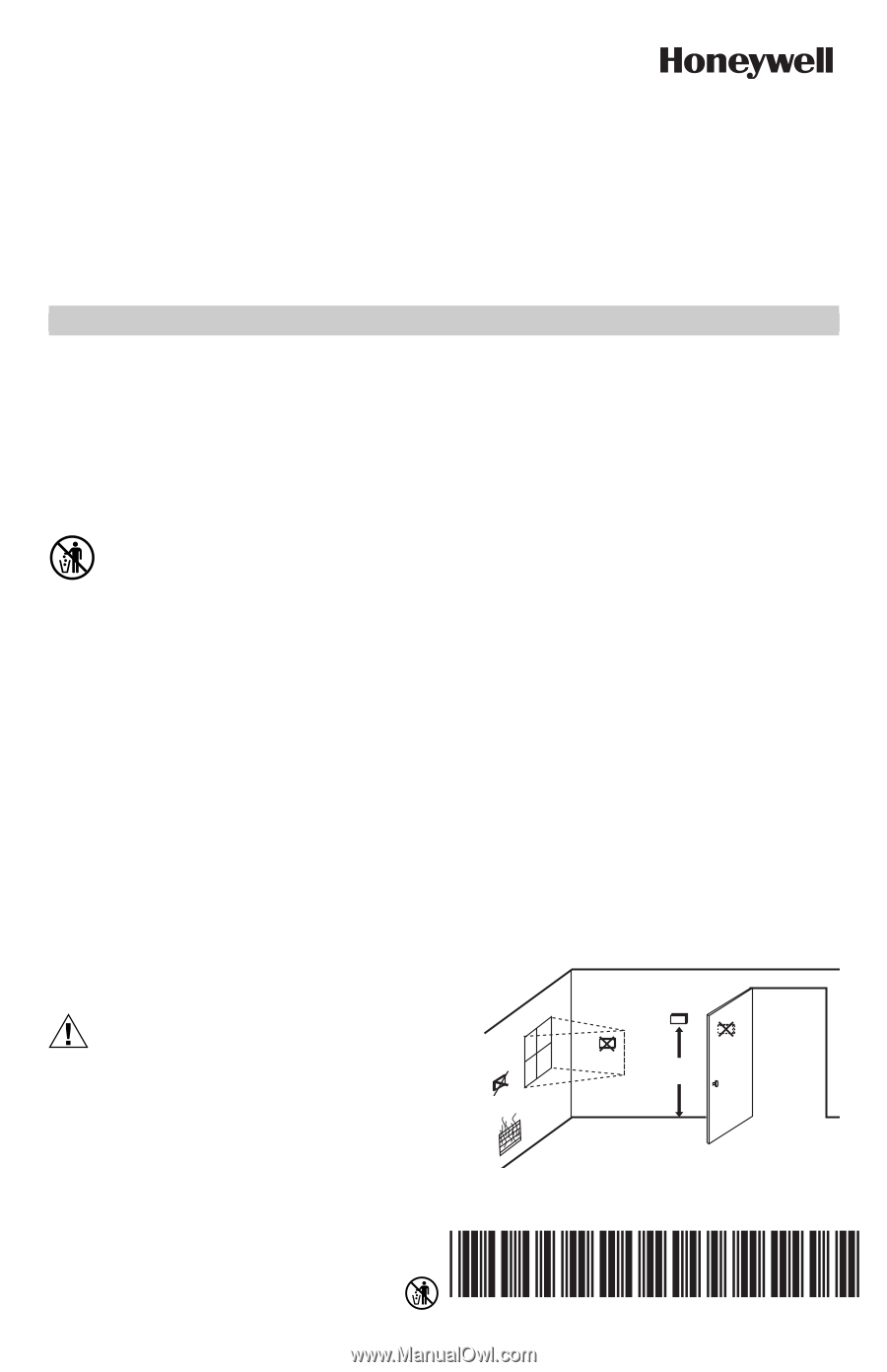
Fig. 1. Typical location of thermostat or
remote-mounted sensor.
5 FEET
(1.5 METERS)
YES
NO
NO
NO
M4823A