Honeywell TH5110D1006 Installation Guide - Page 3
Power options, Wiring
 |
UPC - 085267256988
View all Honeywell TH5110D1006 manuals
Add to My Manuals
Save this manual to your list of manuals |
Page 3 highlights
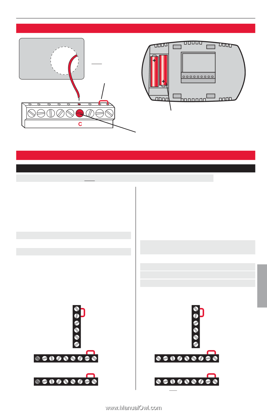
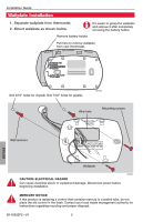
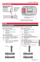
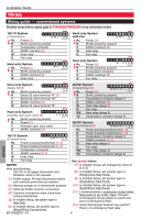
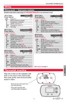
Power options Keep wires in this shaded area Remove factoryinstalled jumper only for twotransformer systems. FocusPRO® TH5000 Series Insert batteries for primary or backup power. Connect C for primary AC power (optional if batteries are installed). M29370 Wiring Terminal designations Shaded areas below apply only to TH5320U/TH5220D or as otherwise noted. Conventional Terminals: Rc 24VAC power from cooling transformer R 24VAC power from heating transformer W Heat relay (stage 1) W2 Heat relay (stage 2) Y Compressor contactor (stage 1) Y2 Compressor contactor (stage 2) G Fan relay C 24VAC common. For 2 transformer systems, use common wire from cooling transformer. TH5110D Rc R Y C W G TH5220D Heat Pump Terminals: Rc 24VAC power from cooling transformer R 24VAC power from heating transformer O/B Changeover valve Y Compressor contactor Y2 Compressor contactor (stage 2) -TH5320U only G Fan relay Aux Auxiliary heat relay* E Emergency heat relay* L Sends output when set to Em. Heat C 24VAC common *Aux and E terminals combined on TH5320U only. TH5110D Rc R Y C O/B G TH5220D Y2 W2 G W C Y R Rc TH5320U L E Aux G O/B C Y R Rc TH5320U Y2 W2 G W C Y R Rc L Y2 Aux E G O/B C Y R Rc M29371 3 69-1922EFS-01 ENGLISH
-
 1
1 -
 2
2 -
 3
3 -
 4
4 -
 5
5 -
 6
6 -
 7
7 -
 8
8 -
 9
9 -
10
-
11
-
12
-
13
-
14
-
15
-
16
-
17
-
18
-
19
-
20
-
21
-
22
-
23
-
24
 |
 |