Hunter 21623 Owner's Manual
Hunter 21623 Manual
 |
View all Hunter 21623 manuals
Add to My Manuals
Save this manual to your list of manuals |
Hunter 21623 manual content summary:
- Hunter 21623 | Owner's Manual - Page 1
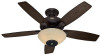
English Concert Breeze™ Owner's Guide and Installation Manual Manual De Propietario Form# 45049-01 20090713 ©2009 Hunter Fan Co. Español - Hunter 21623 | Owner's Manual - Page 2
Speaker 18 12 • Changing the channel on the Maestro™ and the Fan 19 13 • Troubleshooting 20 Welcome Your new Hunter® ceiling fan is an addition to your home or office that will provide comfort and performance for many years. This installation and operation manual gives you complete instructions - Hunter 21623 | Owner's Manual - Page 3
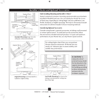
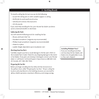
a wall-mounted or remote speed control. To install and use the accessories, follow the instructions included with each product. For quiet and optimum performance of your Hunter fan, use only Hunter speed controls. Support Brace Ceiling Outlet Box For ceilings higher than 8 feet, you can purchase - Hunter 21623 | Owner's Manual - Page 4
, contact your Hunter dealer or call Hunter Technical Support Department at 888-830-1326 (In Canada, call 1-866-268-1936). Preparing the Fan Site Before you begin installing the fan, follow all the instructions in the pullout sheet called "Preparing the Fan Site." Proper ceiling fan location and - Hunter 21623 | Owner's Manual - Page 5
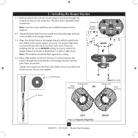
the pilot holes you drilled in the wood support structure. For proper alignment use slotted holes directly across from each other. If you are installing the fan on an ANGLED ceiling, be sure to orient Large Opening LEFT Step 2-3 (Angled Ceiling Only) 5 45049-01 • 07/13/09 • Hunter Fan Company RIGHT - Hunter 21623 | Owner's Manual - Page 6
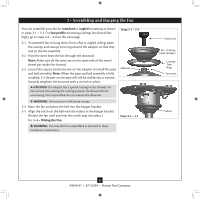
the fan until you hear the notch pop into place.) Go to 4 • Wiring the Fan. Steps 3-4 - 3-5 WARNING: Fan may fall if not assembled as directed in these installation instructions. Downrod Canopy (with Washer) Canopy Trim Ring Setscrew Indent 6 45049-01 • 07/13/09 • Hunter Fan Company - Hunter 21623 | Owner's Manual - Page 7
of the fan assembly. 3-9. Fan may fall if not assembled as directed in these installation instructions. Step 3-6 (Not Actual Size) Steps 3-8 - 3-9 Low Profile Washer Step 3-7 (Detail) Low Profile Washer Adapter Canopy Trim Ring #8-32 x 3/4" Screw Step 3-10 7 45049-01 • 07/13/09 • Hunter Fan - Hunter 21623 | Owner's Manual - Page 8
wire (ungrounded) from the ceiling to the black (ungrounded) and the black/white wire (ungrounded) from the fan CAUTION: Be sure no bare wire or wire strands are visible after making connections. 4-6. Turn the wire side of the outlet box. Wire Connector 8 45049-01 • 07/13/09 • Hunter Fan Company - Hunter 21623 | Owner's Manual - Page 9
canopy trim ring counter clockwise until it releases from canopy. Hanger Bracket Canopy Trim Ring Step 5-4 Step 5-3 Step 5-5 Canopy Screw 9 45049-01 • 07/13/09 • Hunter Fan Company - Hunter 21623 | Owner's Manual - Page 10
Blades Hunter fans use several styles of fan blade irons (brackets that hold the blade to the fan). 6-1. Your fan may include blade grommets. If your fan has mounting screw through the blade iron, and attach lightly to the fan. Insert the second blade mounting screw, then securely tighten both - Hunter 21623 | Owner's Manual - Page 11
7 • Light/Speaker Assembly Installation 7-1. To attach the upper switch housing, partially install two housing assembly screws into the switch housing mounting switch housing fixture falling. Steps 7-1 - 7-4 Housing Assembly Screw Upper Switch Housing 11 45049-01 • 07/13/09 • Hunter Fan Company - Hunter 21623 | Owner's Manual - Page 12
from the two wires in the switch housing labeled "Connect Light Here" or "For Light Use." Lower Switch Housing Threaded Rod Steps 7-5 - 7-6 Wires Light Kit/ Speaker Steps 7-8 - 7-9 Note: Align the fan pull chain with the chain guide. 12 45049-01 • 07/13/09 • Hunter Fan Company - Hunter 21623 | Owner's Manual - Page 13
housing to the white wire from the light kit/ speaker. Secure all wire connections using wire connectors. 7-12.To attach the lower switch housing assembly to the fan, partially install two housing assembly screws into the 7-14 - 7-16 Steps 7-12 - 7-15 13 45049-01 • 07/13/09 • Hunter Fan Company - Hunter 21623 | Owner's Manual - Page 14
into the sockets. 8-3. Place the glass bowl over the light kit/speaker assembly, ensuring the threaded portion of the light kit assembly comes out 13/09 • Hunter Fan Company Threaded Portion of Light Kit Assembly Glass Bowl Steps 8-2 - 8-4 Breakaway Connector Fan Pull Chain Pull Chain Guide Step 8-5 - Hunter 21623 | Owner's Manual - Page 15
use downward air flow pattern In cold weather, use upward air flow pattern To Change Airflow Direction Turn the fan off and let it come to a complete stop. Slide the reversing switch on the fan to the opposite position. Restart fan. Reversing Switch 15 45049-01 • 07/13/09 • Hunter Fan Company - Hunter 21623 | Owner's Manual - Page 16
include Wireless Subwoofers and Duo™ Lamps. Optional accessories can be purchased through Authorized Hunter Dealers. For quiet and optimum performance of your Hunter fan, use only Hunter speed controls. Speaker Wire Installation 300ft (Max. line of sight) NOTE: For Optimal Performance. Place the - Hunter 21623 | Owner's Manual - Page 17
10-6.Make sure that all connections are firm. NOTE: Contact between bare speaker wires at the terminals can cause a short-circuit. 10-7.Install the the FCC rules. Changes or modifications not expressly approved by Hunter Fan Company could void your authority to operate this equipment. Operation - Hunter 21623 | Owner's Manual - Page 18
VOLUME of the speaker. Press to decrease the VOLUME of the speaker. Pressing the will switch the surround sound function between: LED Indicators R Right Channel L Left Channel M Mixed Channel LED Indicators 18 45049-01 • 07/13/09 • Hunter Fan Company - Hunter 21623 | Owner's Manual - Page 19
green/red LED indicators on the bottom of the fan display the channel the fan is tuned to. Green LEDs indicate a good signal and red LEDs indicate no signal. Maestro™ LED Indicators Channel 1 Channel Selection Switch Channel 2 Channel 3 Channel 4 19 45049-01 • 07/13/09 • Hunter Fan Company - Hunter 21623 | Owner's Manual - Page 20
the blade is cracked. If so, replace all the blades. Problem: Excessive wobbling. 1. If your fan wobbles when operating, use the enclosed balancing kit and instructions to balance the fan. 2. Tighten all blade iron screws. 3. Turn power off, support fan very carefully, and check that the hanger
-
 1
1 -
 2
2 -
 3
3 -
 4
4 -
 5
5 -
 6
6 -
 7
7 -
8
-
9
-
10
-
11
-
12
-
13
-
14
-
15
-
16
-
17
-
18
-
19
-
20
 |
 |
Form# 45049-01
20090713
©2009 Hunter Fan Co.
English
Español
Concert Breeze™
Concert Breeze™
Concert Breeze™
Owner’s Guide and Installation Manual
Manual De Propietario